System for monitoring quality of optical signals having different bit rates

a bit rate and optical signal technology, applied in the field of optical signal quality monitoring system, can solve the problems of low measuring efficiency, inability to execute error-rate detection using a single circuit based on the conventional technique, and the possible bit rate of optical signals is limited to approximately 40 gbit/s

Inactive Publication Date: 2002-05-28
NIPPON TELEGRAPH & TELEPHONE CORP
View PDF1 Cites 44 Cited by
  • Summary
  • Abstract
  • Description
  • Claims
  • Application Information

AI Technical Summary

Problems solved by technology

That is, in order to perform error-rate detection corresponding to plural kinds of bit rates, plural circuits which respectively correspond to the different bit rates are necessary, and thus the error-rate detection cannot be executed using a single circuit based on the conventional technique.
However, if the error rate is very low in this method, a long measuring time is necessary and thus the measuring efficiency is low.
Therefore, the possible bit rate of the optical signal is limited to approximately 40 Gbit / s, depending on the range or processing speed of the photoelectric converter and the electrical signal processing circuit.
In addition, the Q-factor at the time when the eye-diagram opening is maximum is measured; thus, the system cannot monitor plural digital optical signals having different bit rates.
Therefore, power loss due to the separation of the optical signal transmitted in the transmission path is generated, thereby degrading the S / N.
According to this arrangement, optical sampling with respect to an optical frequency range is performed using optical means; thus, the quality of optical signals having ultra-high speed of a few dozen Gbit / s or more can be examined, which is difficult using the conventional technique.
Monitoring of optical signals with such high bit rates cannot be realized using the conventional technique.

Method used


Image

  • System for monitoring quality of optical signals having different bit rates
  • System for monitoring quality of optical signals having different bit rates
  • System for monitoring quality of optical signals having different bit rates

Examples


first embodiment

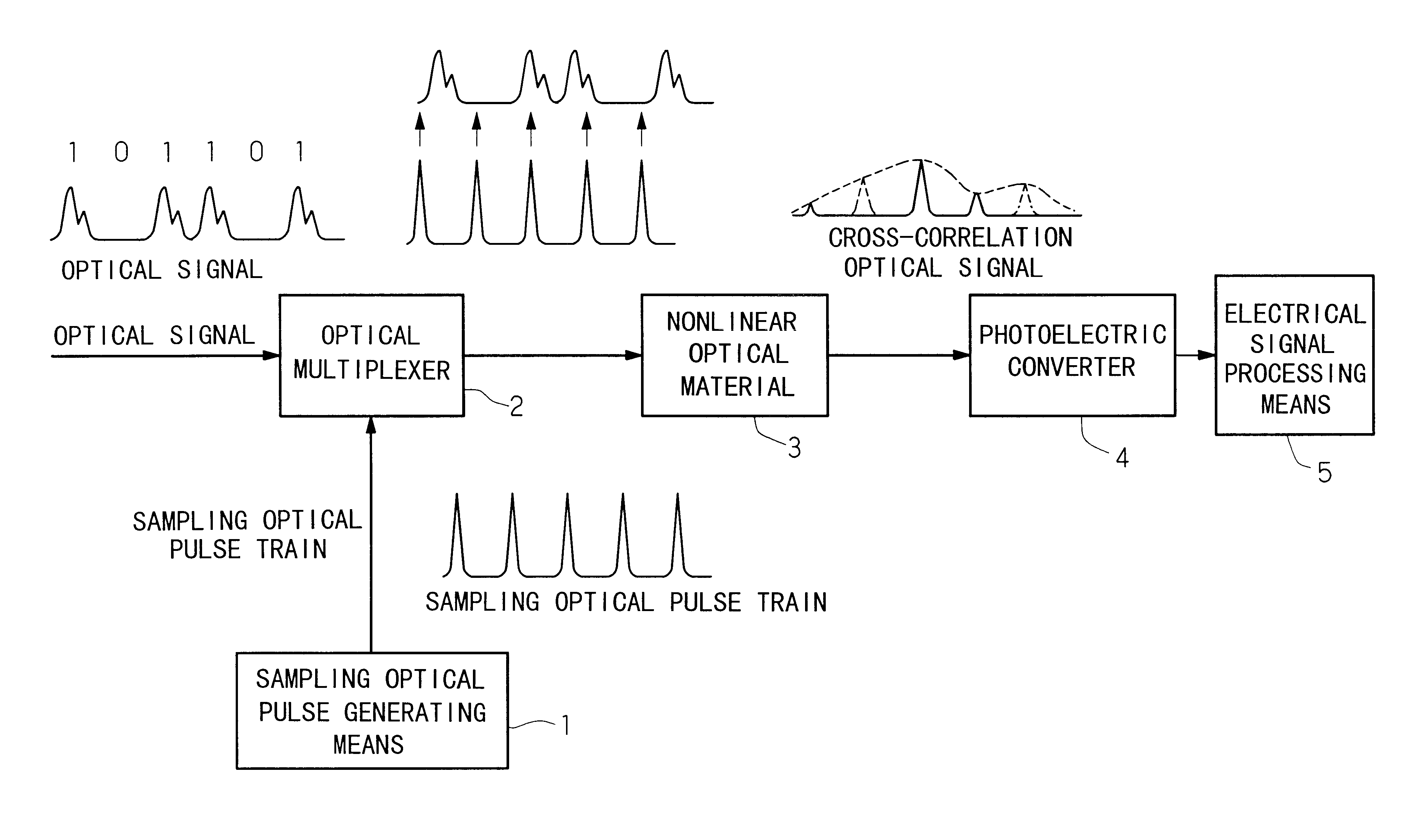
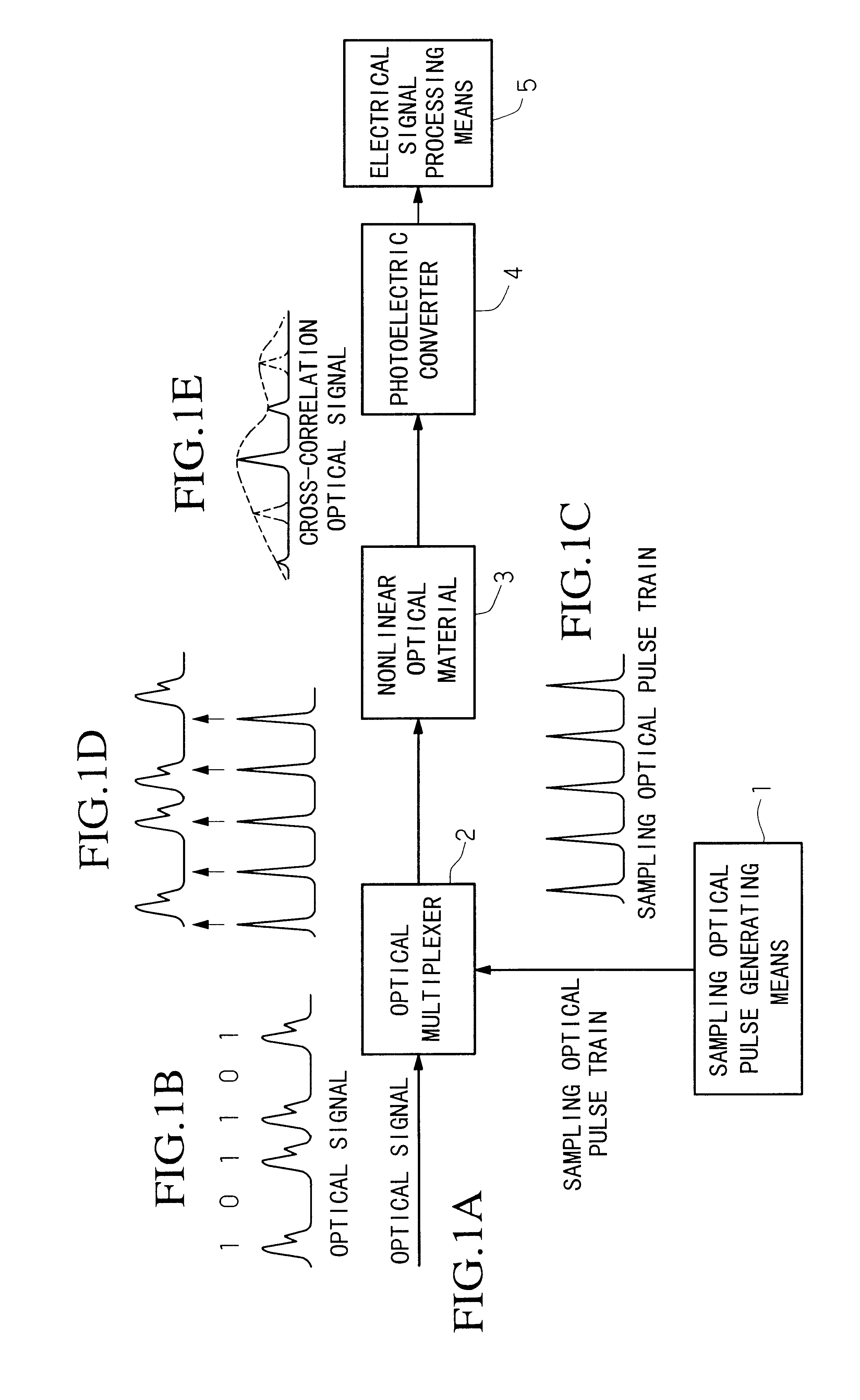
FIG. 8 shows the system for monitoring the quality of an optical signal, according to the present invention.

In the figure, an optical signal having bit rate N.multidot.f.sub.0 (bit / s) which is N (natural number: 1, 2, . . . ) times as much as basic clock frequency f.sub.0 (Hz) is input from a transmission path. A portion of this optical signal is separated by optical coupler 51-1. Preferably, the branch ratio of the monitor port (connected with the monitoring side) of the coupler to the other port connected with the transmission path is set as small as possible so as to prevent the transmission characteristics from degrading due to the power loss caused by the branch operation. The optical signal output from the monitor port of the optical coupler 51-1 is further separated into two portions by optical coupler 51-2.

One portion of the optical signal separated by optical coupler 51-2 is input into timing-clock generator 11. In the generator, basic clock frequency f.sub.0 (Hz) is extrac...

second embodiment

FIG. 11 shows the second embodiment of the system for monitoring the quality of an optical signal, according to the present invention.

The feature of the present embodiment is to use timing-clock generator 16 in place of timing-clock generator 11. The timing-clock generator 16 uses a network-synchronized clock signal having clock frequency f.sub.0 / m (f.sub.0 is the basic clock frequency, and m=1, 2, . . . ), and generates a timing-clock signal of f.sub.0 / n.sub.1 -.DELTA.f (Hz) or f.sub.0 / n.sub.1 +.DELTA.f (Hz) (n.sub.1 =1, 2, . . . ). Here, the offset frequency .DELTA.f can be determined based on the above equation (11). The other structural elements are the same as those of the first embodiment.

The internal structure of the timing-clock generator 16 may comprise, as shown in FIG. 9B, basic bit-rate timing generator 17 for generating the clock frequency f.sub.0 / n.sub.1 using a network-synchronized clock signal having bit rate f.sub.0 / m.

Instead of the timing-clock generator 11 (s...

third embodiment

FIG. 12 shows the third embodiment of the system for monitoring the quality of an optical signal, according to the present invention.

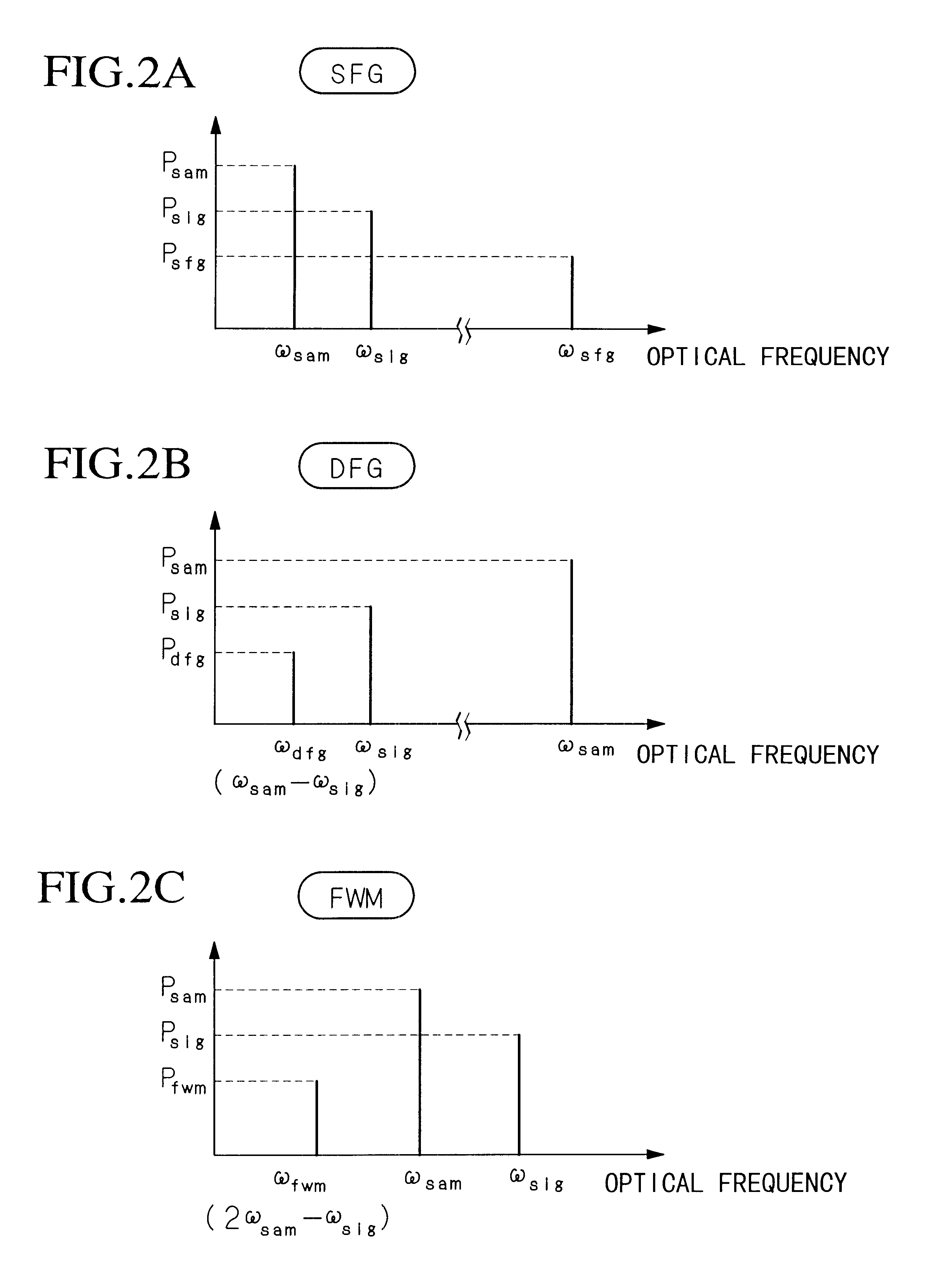
The nonlinear optical effect used in the present invention generally depends on polarization, and the power of the generated cross-correlation optical signal is changed in accordance with the polarization states of the input signals. The polarization dependency can be excluded in the present embodiment.

Therefore, polarization beam splitter 21 having two input ports and two output ports is used in place of optical coupler 2 in the first embodiment. In this case, the optical signal and the sampling optical pulse train are respectively input into these input ports, and a series of nonlinear optical material 3-1, wavelength filter 32-1, and photoelectric converter 4-1 is connected to the first output port, while a series of nonlinear optical material 3-2, wavelength filter 32-2, and photoelectric converter 4-2 is connected to the second output port. The cr...


PUM

PropertyMeasurementUnit
clock frequencyaaaaaaaaaa
frequencyaaaaaaaaaa
pulse repetition frequencyaaaaaaaaaa

Abstract

An optical signal quality monitoring system is provided, by which the quality of optical signals can be examined using a single monitoring system, not depending on the bit rate of each signal. In the system, an optical signal having a bit rate N.f0, that is, N times as much as basic clock frequency f0, is sampled by using a pulse repetition frequency f0/n1-DELTAf or f0/n1+DELTAf where n1 is a predetermined natural number and the pulse repetition frequency slightly differs from f0/n1 by DELTAf, and an amplitude histogram of the optical signal is determined based on results of the sampling. Regarding the sampling points which constitute the histogram, a set of higher-level points and a set of lower-level points are extracted and a ratio of a difference between an average level of the set of higher-level points within a predetermined period and an average level of the set of lower-level points within a predetermined period, to the sum of standard deviations of both sets within each predetermined period is calculated as a coefficient of the S/N, and the quality of the optical signal is examined based on the coefficient. By performing optical sampling, quality of optical signals having bit rates of a few dozen Gbit/s or more can be monitored.

Description

1. Field of the InventionThe present invention relates to an optical signal quality monitoring system for monitoring the signal-to-noise ratio (S / N) of digital optical signals having different bit rates, transmitted in an optical fiber transmission network.This application is based on Patent Applications Nos. Hei 9-330553 and Hei 10-229659 filed in Japan, the contents of which are incorporated herein by reference.2. Description of the Related ArtIn the network hierarchical structure SDH (Synchronous Digital Hierarchy) which was internationally standardized in the 1990s, a parity check called "bit interleave parity (BIP)" is executed between repeaters (this case is called "BIP-8" and is explained later) and also between line terminal multiplexers (this case is called "BIP-N.times.24"), thereby identifying an erroneous section and obtaining a signal for switching and activating operations. Here, "N" (an integer) relates to the level of the multiplex. With the basic symbol "STM-1" indi...

Claims


Application Information

Patent Timeline
Patent Type & Authority Patents(United States)
IPC IPC(8): H04B10/08G01J11/00G02F1/35G01M11/00H04B10/079H04B10/2507H04J3/14H04L25/02
CPCH04B10/07953
Inventor TAKARA, HIDEHIKOYAMABAYASHI, YOSHIAKISHAKE, IPPEI
Owner NIPPON TELEGRAPH & TELEPHONE CORP
Why Eureka
Try Eureka