
Energy saving device for walk-in refrigerators and freezers

a technology for walk-in refrigerators and freezers, which is applied in the direction of lighting and heating apparatus, heating types, domestic cooling apparatus, etc., can solve the problems of inherent delay in the change of temperature associated with the expansion valv

Inactive Publication Date: 2002-06-04
ADRIEL ENERGY
View PDF5 Cites 88 Cited by
  • Summary
  • Abstract
  • Description
  • Claims
  • Application Information

AI Technical Summary

Benefits of technology

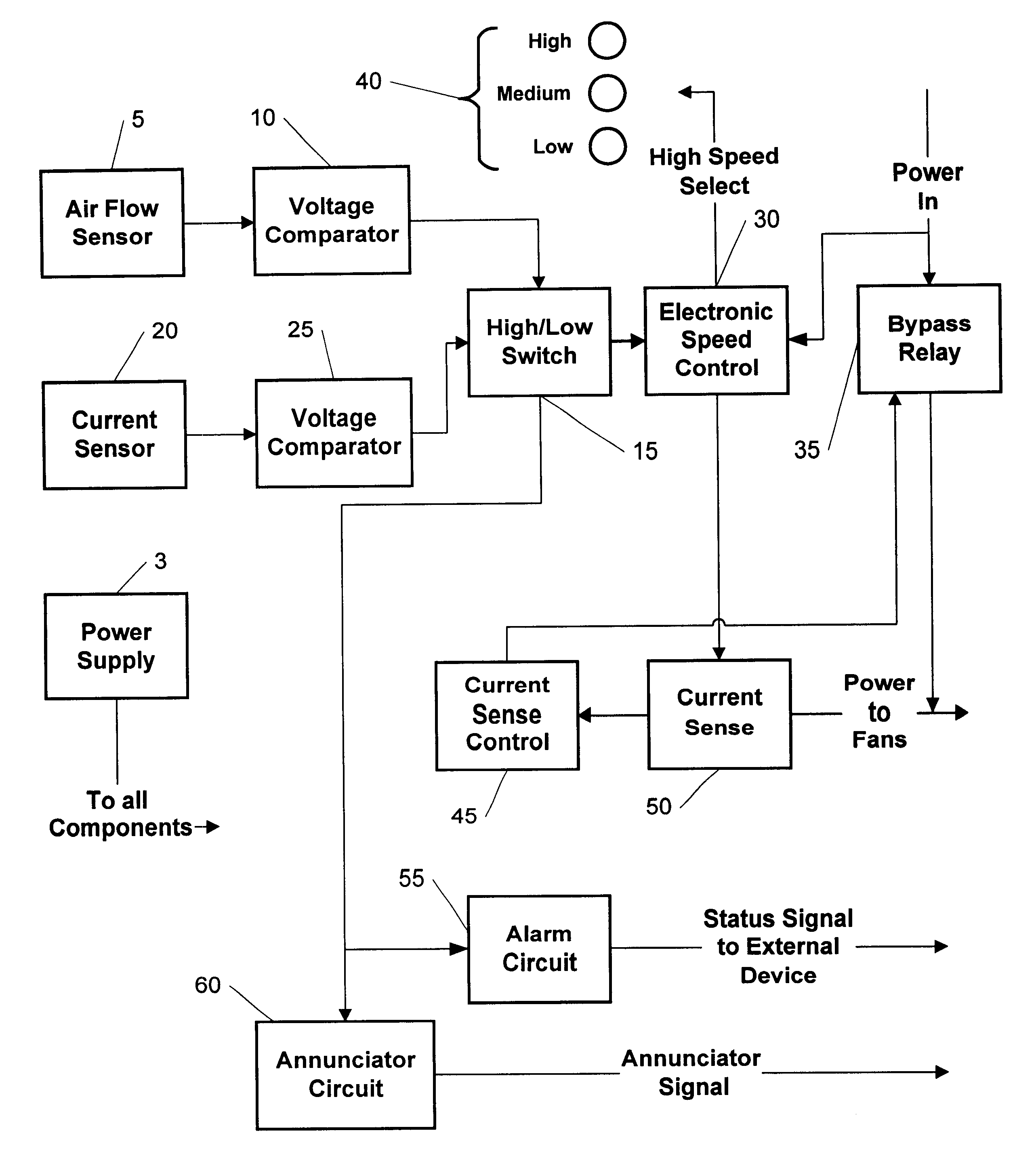
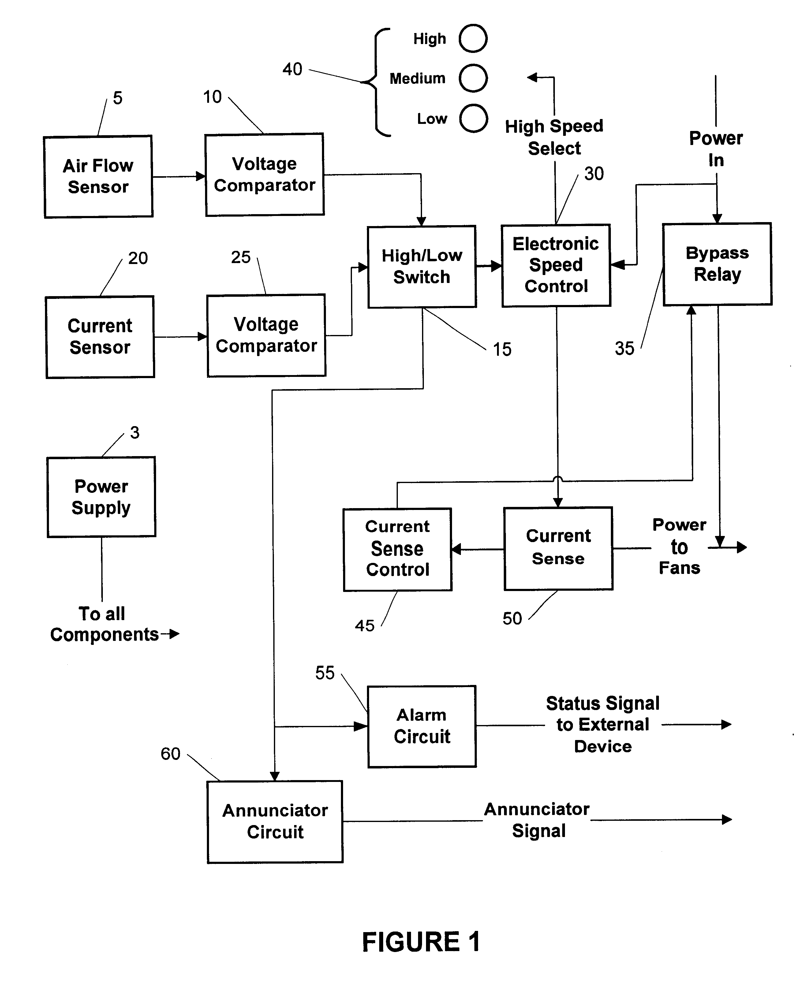
Another object of the present invention is to supply an evaporator fan controller that, based on selected electrical current flow within the controlled refrigeration system, lowers the necessary energy required to operate the refrigeration system by adjusting the fan or fans associated with the evaporator coils to a lower speed when the system is in non-cooling mode and a higher speed or range of speeds when the system is in cooling mode.
Further comprising the subject apparatus is air flow monitor means coupled to the evaporator fan control means, whereby if the air flow over the evaporator falls below a preset value (the decrease in air flow over the evaporator coils may be indicative of icing of the coils or obstruction by dust or dirt) the evaporator fan control means directs the evaporator fan to operate at the high speed to prevent undesirable icing of the evaporator coils.

Problems solved by technology

The drawback to this system is the inherent delay in the change in temperatures associated with the expansion valve.

Method used


Image

  • Energy saving device for walk-in refrigerators and freezers
  • Energy saving device for walk-in refrigerators and freezers
  • Energy saving device for walk-in refrigerators and freezers

Examples


Embodiment Construction

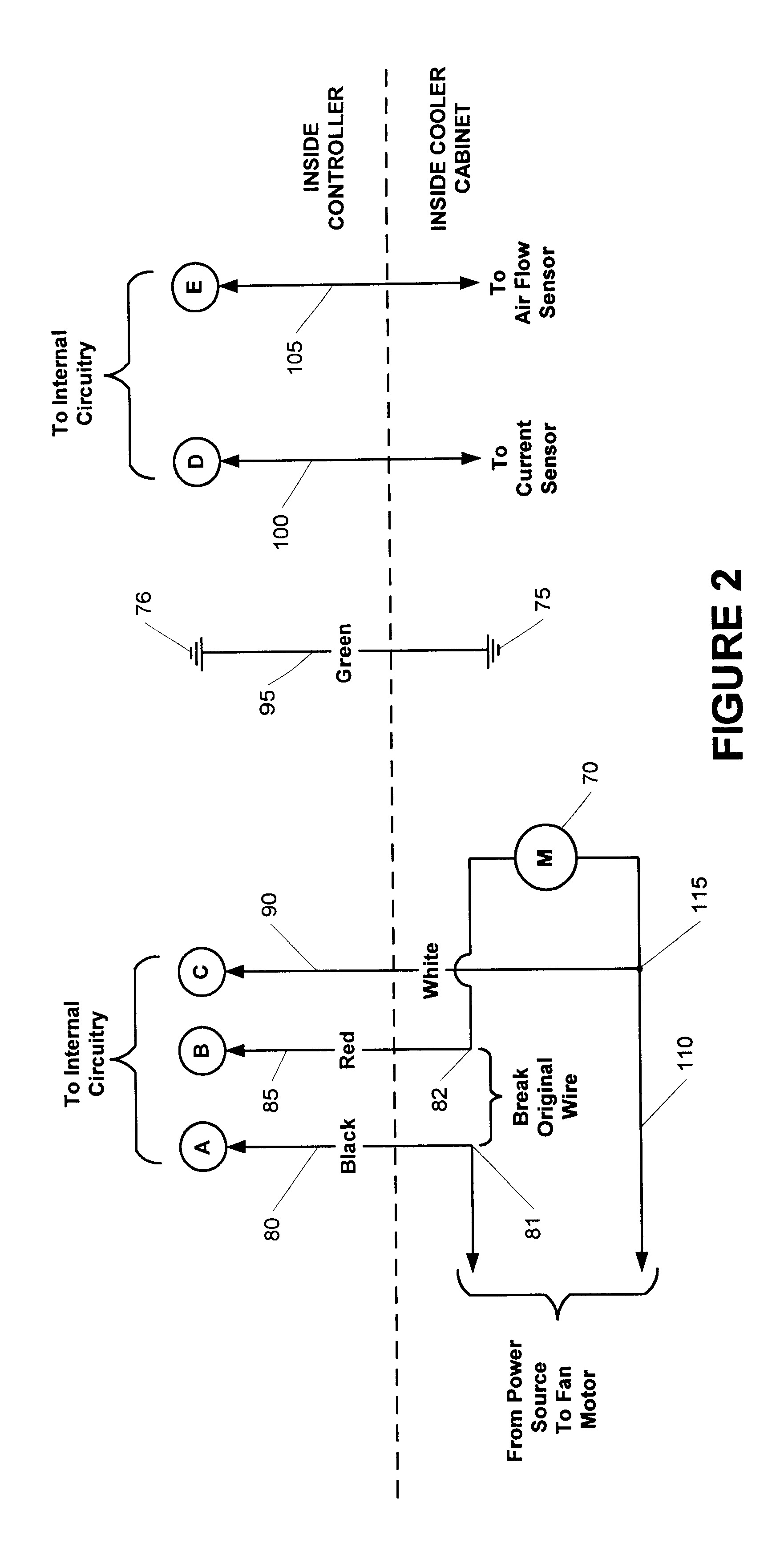
By way of example and not by way of limitation, a working example of the subject invention is now related in FIGS. 2-7. The various exemplary components and values, if applicable to a component, are all listed in the included tables (TABLES 1-3) with each functioning in its own customary manner. Shown in FIG. 2 (and associated TABLE 1) are the typical connections between the subject controller and the refrigeration system (it must be remembered that equivalent connections are also considered to be within the realm of this disclosure). The top portion of FIG. 2 illustrates connections inside the controller, while the lower portion of FIG. 2 depicts connections inside the chamber / cabinet which contains the evaporator coils and fans. The evaporator fan motor 70 is adapted to have the controller coupled into its power supply by breaking an original wire between points 81 and 82 and adding wires 80, 85, and 90 that run to the internal controller circuitry at locations A, B, and C. A comm...


PUM


Abstract

An energy saving apparatus for use with a heat exchange system having a cooled chamber, a compressor, a condenser, an evaporator, an evaporator fan, and refrigerant within refrigerant carrying lines has an evaporator fan controller for monitoring operational status of the system (cooling or non-cooling) and setting an energy saving operational speed for the evaporator fan based on the operational status of the system (cooling or non-cooling) and a current sensor coupled to the evaporator fan controller for detecting the operational status of the system (cooling or non-cooling). If the system is detected as cooling, the evaporator fan controller directs the evaporator fan to operate at a high speed and if the system is detected as not cooling (non-cooling), the evaporator fan controller decreases the operational speed of the evaporator fan to a low speed, thereby decreasing evaporator fan produced heat, resulting in an overall decreased energy requirement for the heat exchange system.

Description

1. Field of the InventionAn evaporator fan controller is provided to lower energy use in a heat exchange system. More specifically, an evaporator fan controller, for initial installation or retrofit, monitors the cooling cycle of a refrigeration system and adjusts the operation of an associate fan to maximize energy efficiency.2. Description of the Background ArtCompressor-associated refrigeration systems function by removing heat from a desired location, thereby cooling that location. For example, in a walk-in type refrigerator, often, more than 30% of the heat found in the location to be cooled is actually generated by fan motors within the refrigeration system itself. A typical walk-in refrigerator may have an evaporator coil fitted with five motors of standard configuration. If these motors are rated at a typical value of 1 / 20 hp each, their combined heat output would be approximately 11,675 Btu / hr, at normal operating voltage. Clearly, if this amount of system generated heat co...

Claims


Application Information

Patent Timeline
IPC IPC(8): F24F11/00F25D29/00F25D17/06
CPCF24F11/0079F25D29/00F25D17/06F25B2600/112F25B2700/15Y02B30/746Y02B30/743F24F11/77Y02B30/70
Inventor KERNKAMP, JOHN H.LINDER, E. E.KERSTEN, ED
Owner ADRIEL ENERGY
Learn More