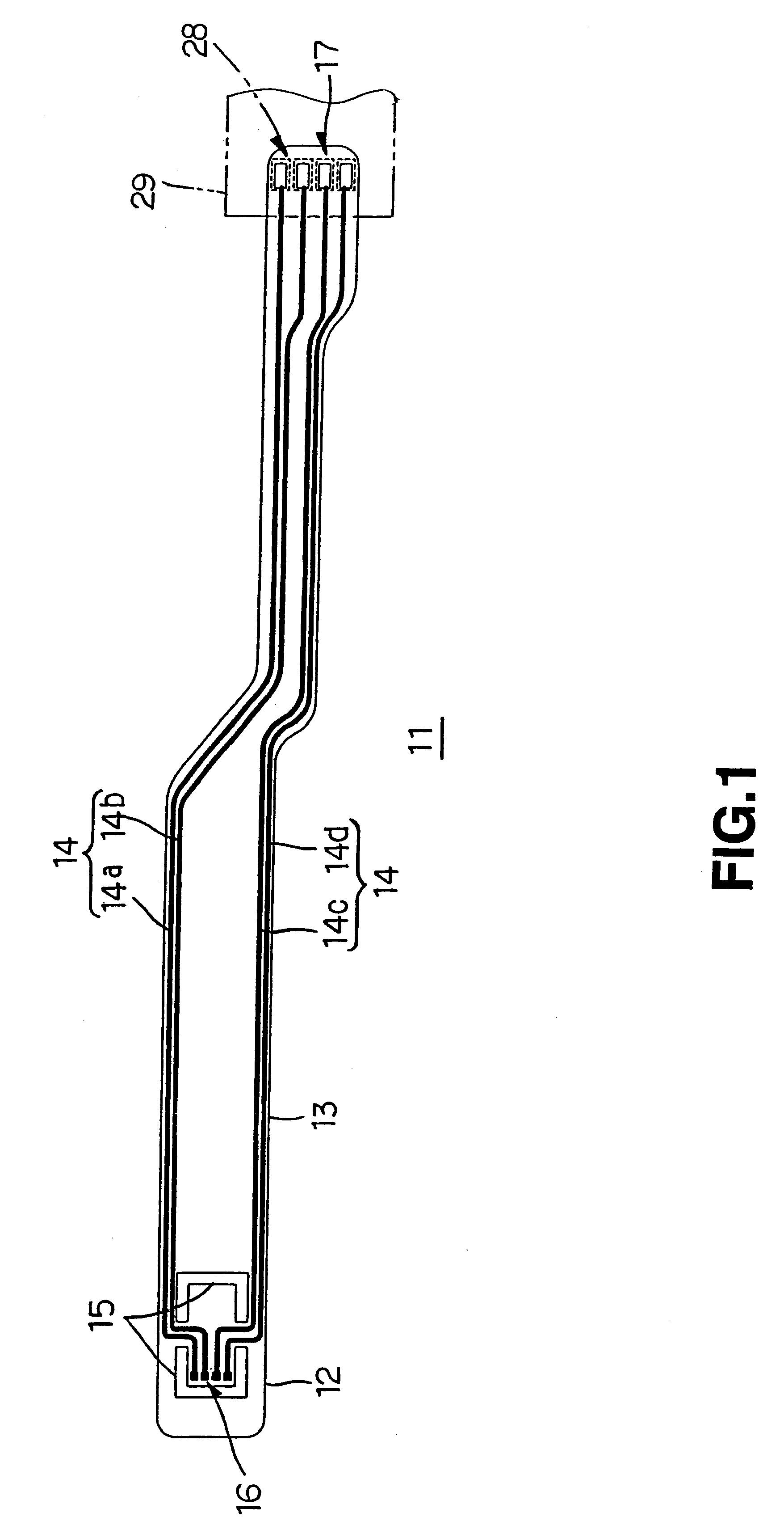
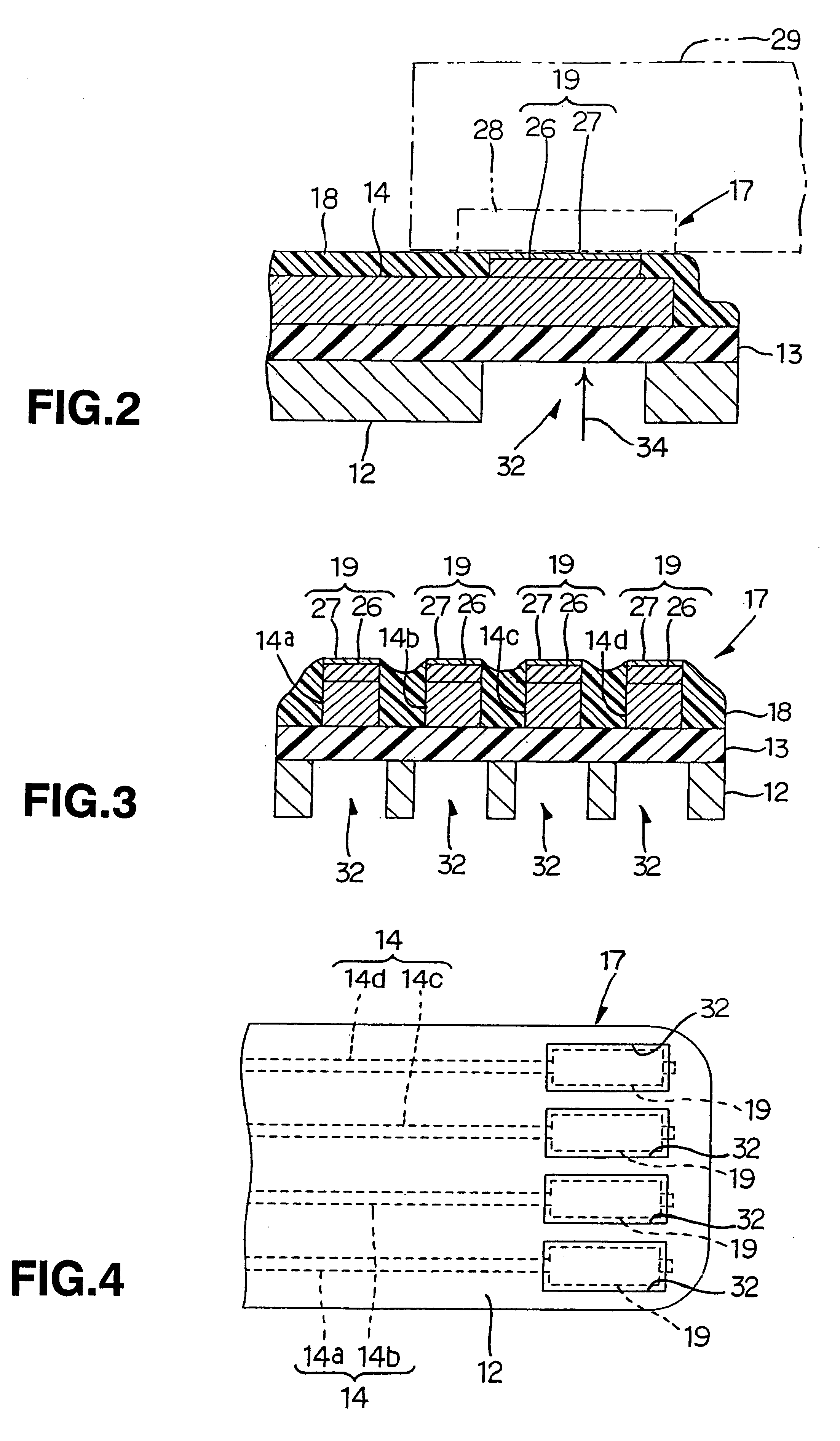
Suspension board with circuit
a suspension board and circuit technology, applied in the direction of insulating substrate metal adhesion improvement, maintaining head carrier alignment, instruments, etc., can solve the problems of not being able to bond to each other with sufficient strength, and sometimes not being able to achieve sufficient bonding reliability, sufficient strength, and simple structur
- Summary
- Abstract
- Description
- Claims
- Application Information
AI Technical Summary
Benefits of technology
Problems solved by technology
Method used
Image
Examples
example 1
Liquid solution of polyamic acid resin was applied on the stainless foil having thickness of 25 .mu.m and then heated at 130.degree. C. to thereby form a coating of polyamic acid resin. Sequentially, the coating was exposed to light (405 nm, 1,500 mJ / cm.sup.2) through the photomask. The exposed part was heated to 180.degree. C. and then developed by using alkaline developer, whereby the coating was patterned with the negative image. Sequentially, the patterned coating of polyamic acid resin was heated at 350.degree. C. to be cured (imidized), whereby the base layer made of polyimide of thickness of 15 .mu.m was formed with the specified pattern.
Sequentially, a thin chrome film of thickness of 300 .ANG. and a thin copper film of thickness of 700 .ANG. were formed in sequence on the entire surface of the stainless foil and the base layer by the sputtering deposition process. Thereafter, the plating resist having the opposite pattern to the specified circuit pattern was formed by use o...
example 2
The suspension board with circuit was produced in the same operation as in Example 1, except that when the stainless foil was cut out by the chemical etching, it was opened to form a single, large, rectangular opening to contain all the pad portions, rather than was opened in its portions corresponding to the pad portions separately.
The suspension board with circuit of Example 2 corresponds in external connection terminal to the embodied form shown in FIGS. 9 and 10.
example 3
Liquid solution of polyamic acid resin was applied on the stainless foil having thickness of 25 .mu.m and then heated at 130.degree. C. to thereby form a coating of polyamic acid resin. Sequentially, the coating was exposed to light (405 nm, 1,500 mJ / cm.sup.2) through the photomask. The exposed part was heated to 180.degree. C. and then developed by using alkaline developer, whereby the coating was patterned with the negative image. In this patterning process, the coating was kept from being formed at its portions where the pad portions of the external connection terminals were formed. Sequentially, the patterned coating of polyamic acid resin was heated at 350.degree. C. to be cured (imidized), whereby the base layer made of polyimide of thickness of 15 .mu.m was formed with the specified pattern.
Sequentially, a thin chrome film of thickness of 300 .ANG. and a thin copper film having thickness of 700 .ANG. were formed in sequence on the entire surface of the stainless foil and the ...
PUM
| Property | Measurement | Unit |
|---|---|---|
| Force | aaaaa | aaaaa |
| Force | aaaaa | aaaaa |
| Force | aaaaa | aaaaa |
Abstract
Description
Claims
Application Information
 - R&D
- Intellectual Property
- Life Sciences
- Materials
- Tech Scout
- Unparalleled Data Quality
- Higher Quality Content
- 60% Fewer Hallucinations
Browse by: Latest US Patents, China's latest patents, Technical Efficacy Thesaurus, Application Domain, Technology Topic, Popular Technical Reports.
© 2025 PatSnap. All rights reserved.Legal|Privacy policy|Modern Slavery Act Transparency Statement|Sitemap|About US| Contact US: help@patsnap.com


