Arbitrarily positioned lateral perforation forming apparatus for form printing machine

a technology of lateral perforation and forming apparatus, which is applied in the direction of printing, stock shearing machine, manufacturing tools, etc., can solve the problems of lateral perforation, error in perforation forming position, and inability to form lateral perforation, so as to simplify the control system and accurately form lateral perforation

Inactive Publication Date: 2002-06-11
MIYAKOSHI PRINTING MACHINERY
View PDF25 Cites 17 Cited by
  • Summary
  • Abstract
  • Description
  • Claims
  • Application Information

AI Technical Summary

Benefits of technology

The present invention has been worked out in view of the drawbacks in the prior art set forth above. Therefore, it is an object of the present invention to provide an arbitrarily positioned lateral perforation forming apparatus which can form lateral p

Problems solved by technology

Therefore, it has not been possible to form the lateral perforation only for preliminarily selected image.
However, due to an inertia load of the lateral roulette cylinder and an impact upon the formation of perforation, the rotation and perforation formation may be performed in a condition where the position of the roulette edge is dislocated from the position synchronized with the signal to cause an error in the perforation forming position in the product.
However, it causes a problem that the lateral perforation is not formed for a deflecting deformation of the lateral roulette cylinder.
Then, a drive control portion for the servo motor having large capacity has to be used to perform the accurate synchronization, to result in high cost.
However, the latter prior art encounters the following problem.
Namely, since the bearing box supporting the lateral roulette cylinder rotates eccentrically relative to the center of the lateral roulette cylinder at every time of formation of lateral perforation, a play should be caused by wearing in a

Method used


Image

  • Arbitrarily positioned lateral perforation forming apparatus for form printing machine
  • Arbitrarily positioned lateral perforation forming apparatus for form printing machine
  • Arbitrarily positioned lateral perforation forming apparatus for form printing machine

Examples


Embodiment Construction

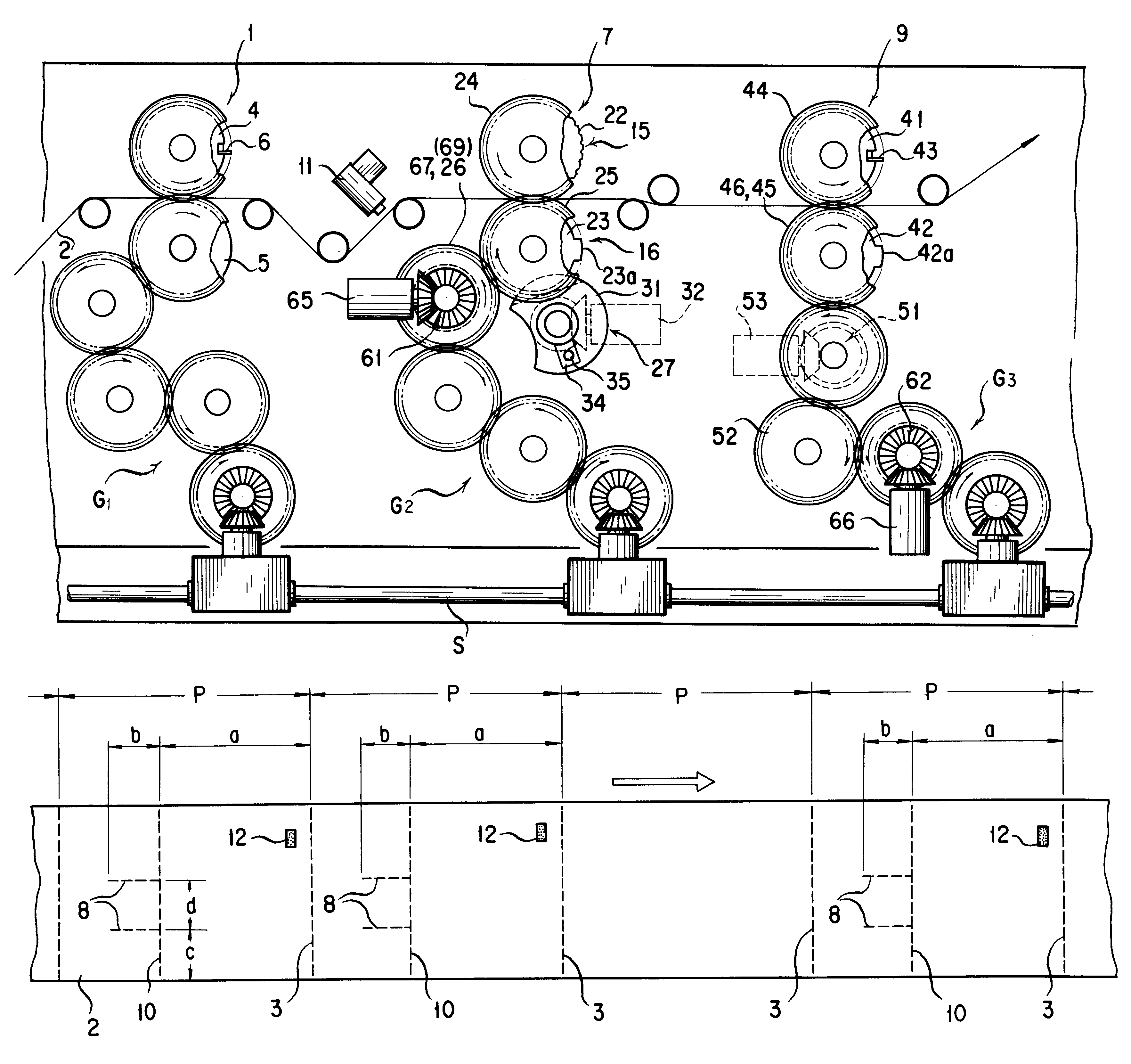
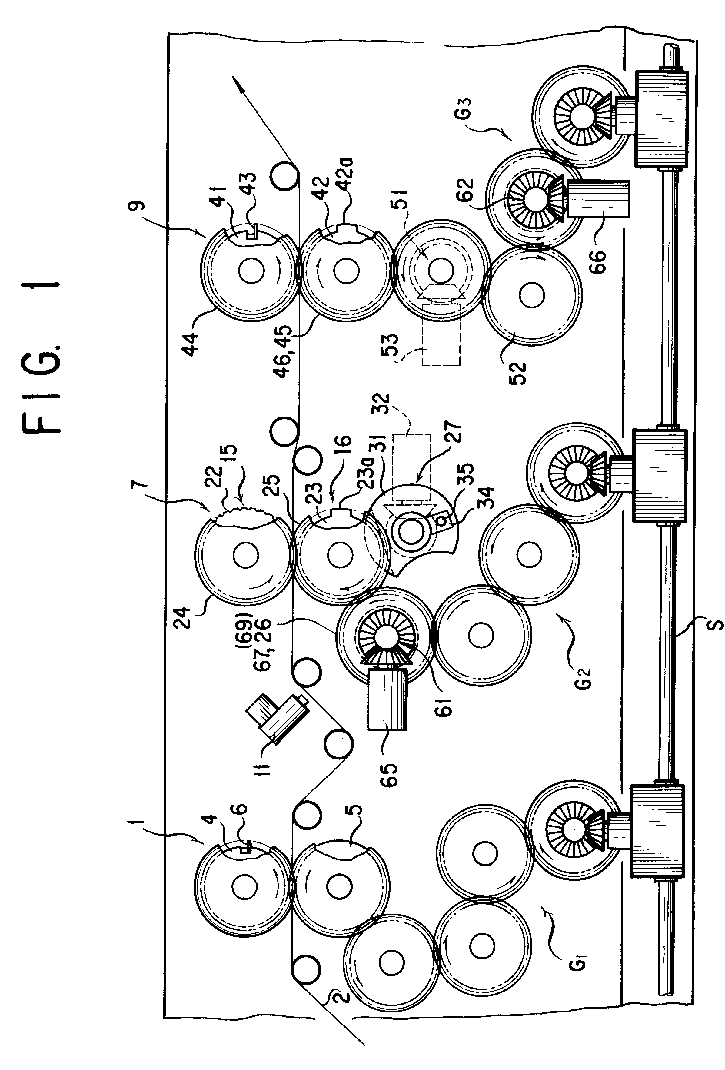
The present invention will be discussed hereinafter in detail in terms of the preferred embodiment of the present invention with reference to the accompanying drawings, i.e. FIGS. 1 to 10. In the following description, numerous specific details are set forth in order to provide a thorough understanding of the present invention. It will be obvious, however, to those skilled in the art that the present invention may be practiced without these specific details. In other instance, well-known structures are not shown in detail in order to avoid unnecessarily obscure the present invention.

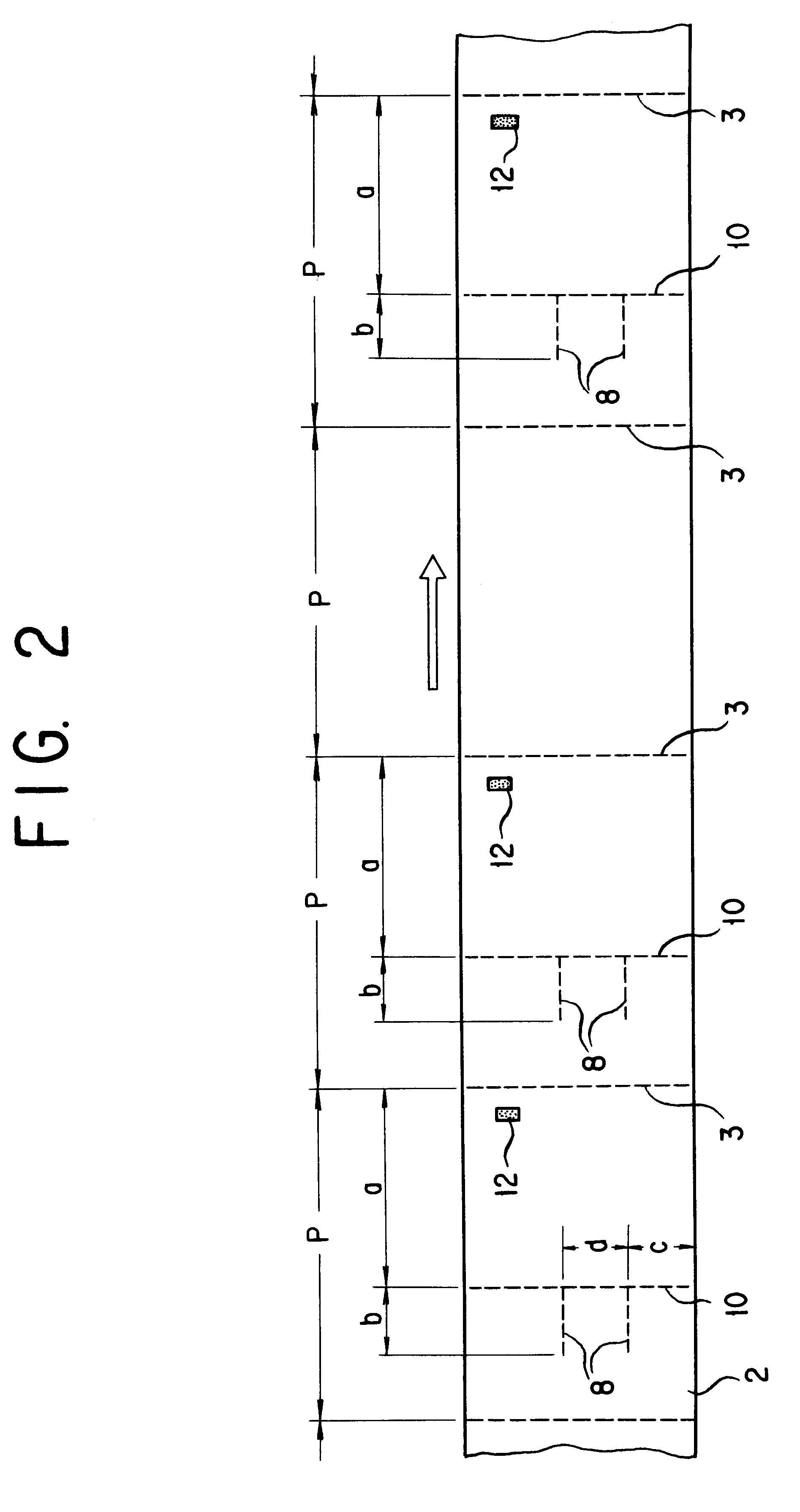
In the drawings, the reference numeral 1 denotes a fold line lateral perforation forming apparatus for forming a lateral perforation 3 for a fold line in a continuous web paper 2 which is fed sequentially, at predetermined interval as shown in FIG. 2. The lateral perforation forming apparatus has a construction well known in the art and comprises a fold line lateral roulette cylinder 4 and a receptacle c...


PUM


Abstract

An arbitrarily positioned lateral perforation forming apparatus can form a lateral perforation at an arbitrary position or selected position in a continuous web paper at high precision by a simple control system with small control amount. A lateral roulette cylinder projecting a lateral roulette edge on its outer periphery, arranged on one side of the continuous web paper and rotating in a traveling direction of the continuous web paper; and a receptacle cylinder projecting an edge projecting portion opposing to the lateral roulette edge of the lateral roulette cylinder on its outer periphery, arranged on the other side of the continuous web paper, rotating in the traveling direction of the continuous web paper, and forming a lateral perforation in the continuous web paper when the edge receptacle portion opposes the roulette edge; are rotated in synchronism with traveling of the continuous web paper in the drive system. Furthermore, the arbitrarily positioned lateral-perforation forming apparatus includes a first differential mechanism disposed in an element connected to one of the lateral roulette cylinder and the receptacle cylinder in the drive system, causing difference in rotational phases of the lateral roulette cylinder and the receptacle cylinder by varying rotation of a differential shaft thereof for selectively placing the edge receptacle portion at a position opposing to the roulette edge and a position circumferentially offsetting from the roulette edge, and a first control unit for controlling rotation of the differential shaft of the first differential mechanism.

Description

BACKGROUND OF THE INVENTION1. Field of the InventionThe present invention relates generally to a lateral perforation forming apparatus for a form printing machine. More particularly, the invention relates to an arbitrarily positioned lateral perforation forming apparatus for forming a lateral perforation at an arbitrary position or a selected position in a continuous web paper printed by a form printing machine, depending upon a printed image.2. Description of the Related ArtSince a form printing machine performs a printing by means of a plate cylinder having a predetermined peripheral length, printing on a continuous web paper repeatedly makes a print per predetermined length in a feeding direction of the continuous web paper, namely makes repeated prints of the same image. Then, when a lateral or cross line perforation aligned in a perpendicular direction to a longitudinal direction of the continuous web paper is formed in a part of the printed image of such repeated prints of the...

Claims


Application Information

Patent Timeline
IPC IPC(8): B26D1/62B26D1/01B26D1/00B26D1/40B26D7/20B26D7/26B26D5/32B26D5/20B26F1/00B26D7/00B26F1/20B26D9/00B41F19/08
CPCB26D1/405B26D1/626B26D5/32B26D7/20B26F1/20B26D9/00B26D7/2635B26D2001/623B26D2007/202B26D2007/2657Y10T83/543Y10T83/4682Y10T83/4737Y10T83/533Y10T83/4656
Inventor KISHINE, TOSHIAKIIZAWA, HIDEOYOSHIKAWA, MIKIO
Owner MIYAKOSHI PRINTING MACHINERY
Why Eureka
Try Eureka