Water-cooling panel for furnace wall and furnace cover of arc furnace

a technology for furnace walls and furnace covers, which is applied in the direction of furnaces, furnace crowns/roofs, servomotors, etc., can solve the problems of increased wear and tear of refractory used in furnace bodies and roofs, increased refractory-related costs, and more downtime for refractory repair

Inactive Publication Date: 2002-06-11
NIPPON STEEL CORP
View PDF23 Cites 26 Cited by
  • Summary
  • Abstract
  • Description
  • Claims
  • Application Information

AI Technical Summary

Problems solved by technology

Since electric-arc furnace power consumption rose in proportion, wear and tear on the refractory used in the furnace body and roof increased markedly.
The result was higher refractory-related costs and more downtime for refractory repair.
During use for several hundred to one thousand charges, therefore, the casting experiences cracking caused by thermal stress and becomes brittle owing to change in texture.
As the cracking and embrittlement proceed, the casting undergoes wear and the bricks within the casting drop out.
When the cracks occurring in the casting surface propagate as far as the cooling water pipe(s), water leakage occurs.
Still, since the bricks are embedded in the panel on the furnace interior side and the pipe or pipes are present behind the bricks, the ends of the bricks on the furnace interior side reach a high temperature that causes them to wear rapidly.
The panel proper also has greater weight owing to its larger thickness.
The material cost is therefore higher than when cast iron is used, especially in the case of a very large copper casting.
Because of this, the problem of texture change and cracking of the casting cannot be overcome.
This method also increases cost because complicated fabrication steps are required in order to cast the low-melting-point metal, which has different properties from the cooler proper, around the cooling water pipe.
Because of the texture change and cracking of the casting, along with other problems, the cast cooler of this structure has not come into general use.
During operation, the refractory roof 23 incurs fusion damage under high-temperature heating and has to be replaced.
This increases cost.
This structure prolongs the service life of the furnace roof.
Still, owing to the occurrence of cracks with continuing operation of the electric-arc furnace, this water-jacket type furnace roof made of steel plate frequently experiences water leakage from the water jacket.
Moreover, in an electric-arc furnace whose wall and roof are formed with water jackets made of steel plate, the amount of heat lost to water cooling accounts for about 10% of the total energy required by the electric-arc furnace.
However, the furnace roof of this structure has the same problems as pointed out regarding the furnace body cooler describe earlier.
During use for several hundred to one thousand charges, therefore, the casting experiences cracking caused by thermal stress and becomes brittle owing to change in texture.
As the cracking and embrittlement proceed, the casting undergoes wear and the bricks within the casting wear and drop out.
When the cracks occurring in the casting surface propagate as far as the cooling water pipe(s), water leakage occurs.
Therefore, like the furnace body cooler, the furnace roof cooler is also susceptible to cracking of the steel plate and the steel pipework portion as well as to the water leakage this causes.
Problems therefore persist regarding heat loss to the cooling water and the need for a high-power pump for supplying the cooling water.
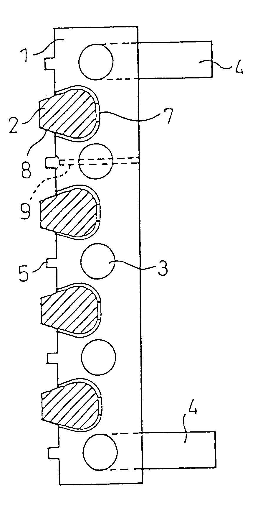
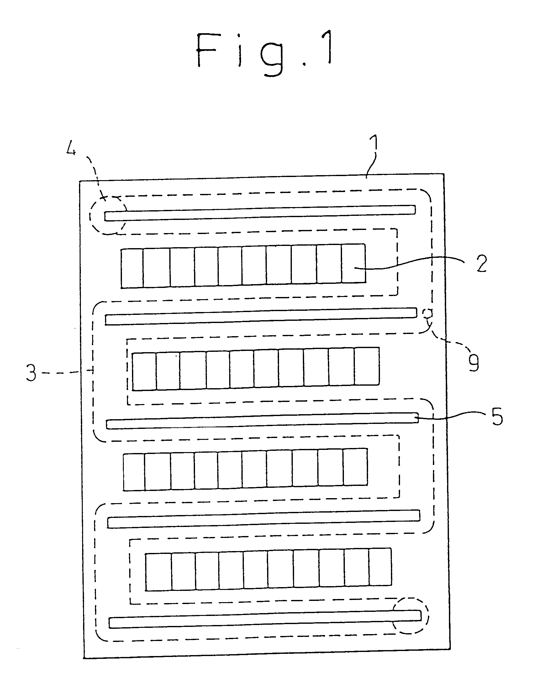
The conventional furnace body cooler composed of one or more cooling water pipes and bricks integrally embedded in an iron casting (Japanese Unexamined Published Patent Application 49-118635) experiences cracking caused by thermal stress and becomes brittle owing to a change in texture.
As the cracking and embrittlement proceed, the casting undergoes wear and the bricks within the casting drop out.
In the cooling structure using cast copper, although no cracking arises because of thermal stress and no embrittlement is caused by change in the casting structure, the ends of the bricks on the furnace interior side wear rapidly because they are not cooled.
Moreover, it has not been possible to avoid gradual, progressive oxidative wear of the refractory brick surfaces in a high temperature atmosphere and / or mechanical damage to the refractory bricks under the impact of scrap charged into the electric-arc furnace.
Therefore, when brick wear proceeds to the point that the effect of reducing heat loss to the cooling water can no longer be obtained, the water-cooled panel proper has to be removed and replaced.
The old water-cooled panel, which cannot be refurbished with new refractory bricks, has to be scrapped.
This is another disadvantage.
In the case of the furnace roof, however, the slag and other furnace deposits tend to fall into the furnace, making stable retention difficult.
The reduction of heat loss to the cooling water is therefore less reliable when the panel is applied to the furnace roof than when it is applied to the furnace wall.
Moreover, the more frequent exposure of the bricks embedded in the panel to the furnace interior accelerates brick wear.

Method used


Image

  • Water-cooling panel for furnace wall and furnace cover of arc furnace
  • Water-cooling panel for furnace wall and furnace cover of arc furnace
  • Water-cooling panel for furnace wall and furnace cover of arc furnace

Examples


Embodiment Construction

The invention water-cooled panel for use in the wall and roof of an electric-arc furnace will now be explained with reference to the drawings.

FIGS. 1-3 show a water-cooled panel 1 for use in the wall and roof of an electric furnace that is an embodiment of the present invention. Water inlet / outlet pipes 4, rows of refractory bricks 2 and a unitary cooling water pipe 3 installed between the rows of refractory bricks 2 are embedded in a casting. The distance between the cooling water pipe 3 and the surface of the casting of the water-cooled panel proper 1 on the furnace interior side is short. The surface of the casting on furnace interior side can therefore be efficiently cooled.

On the furnace interior side, the refractory bricks 2 embedded in the water-cooled panel 1 project from the casting surface into the interior of the furnace. The surface of the water-cooled panel on the furnace interior side is therefore irregular. This permits slag and other furnace molten matter 6 to adhere...


PUM

PropertyMeasurementUnit
temperatureaaaaaaaaaa
surface temperatureaaaaaaaaaa
temperatureaaaaaaaaaa

Abstract

A water-cooled panel for the furnace wall and furnace roof of an electric-arc furnace is integrally fabricated of refractory bricks arrayed on the furnace inner wall in multiple regularly spaced rows to be exposed at the end surfaces and cooling water pipes installed between the rows of refractory bricks (2). A furnace exterior side of the refractory bricks and a furnace interior side of a cooling water pipe are overlapped in a vertical direction of the water-cooled panel, and the cooling water pipe is provided in between an upper and lower side of refractory bricks.

Description

This invention relates to a water-cooled wall and roof panel for installation in an electric-arc furnace used for melting metal material and refining molten metal.BACKGROUND TECHNOLOGYIn electric-arc furnaces used to melt metal materials and refine molten metal up to the mid-1970s, the furnace body was lined with refractory at the inside of shell and the roof used arch-like refractory at the inside of a metal frame called a furnace roof frame. From around the latter half of the 1970s, however, the need to increase productivity led to a rapid increase in electric-arc furnace size. Since electric-arc furnace power consumption rose in proportion, wear and tear on the refractory used in the furnace body and roof increased markedly. The result was higher refractory-related costs and more downtime for refractory repair.One attempt made to overcome these problems was aimed at extending the refractory service life while minimizing a decrease in electric-arc furnace heat efficiency by using ...

Claims


Application Information

Patent Timeline
Patent Type & Authority Patents(United States)
IPC IPC(8): E02F9/22F15B11/00F15B11/16F27D1/12F27B3/10F27B3/24F27D9/00
CPCE02F9/2225E02F9/2282F27D1/12F27B3/24F27D2009/0062F27D2009/0045F27D2009/0048F27D2009/0051F27D2009/0054F27D2009/0032
Inventor MORI, TADASHIUCHIDA, SHINJIROKIRISHIKI, KOICHI
Owner NIPPON STEEL CORP
Why Eureka
Try Eureka