
Method of power supply for electronic systems and device therefor

a technology of electronic systems and power supply sources, applied in the direction of electric variable regulation, electric generators/motors, instruments, etc., can solve the problems of limited service life of galvanic sources, high cost, and restricting the use of power supply sources

Inactive Publication Date: 2002-06-18
NUNUPAROV MARTYN SERGEEVICH
View PDF15 Cites 46 Cited by
  • Summary
  • Abstract
  • Description
  • Claims
  • Application Information

AI Technical Summary

Benefits of technology

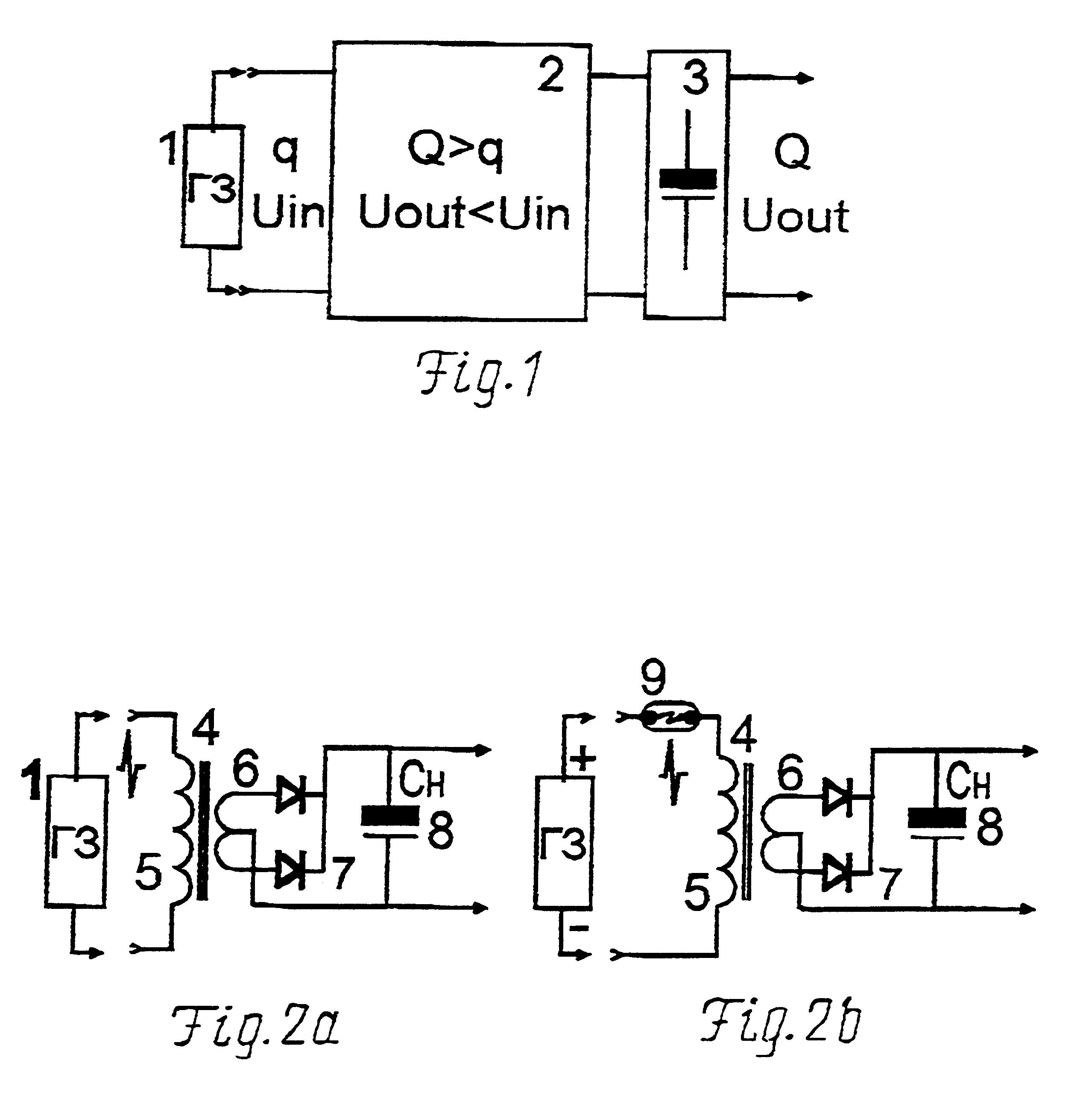
An apparatus that embodies such method of power supply for electronic systems, comprising a generator of electric charges which converts energy of the non-electric nature into the electric energy of charges having a high electric potential, and an electric charges storage, according to this invention further comprises a converter of energy of these charges, input of which converter is connected to output of a charge generator, and output of said converter is connected to input of the electric charge storage, output of which storage is the output of the apparatus. The charge energy converter is capable of increasing the quantity of the initial electric charges coming to its input from the charge generator, and of decreasing their electric potential.
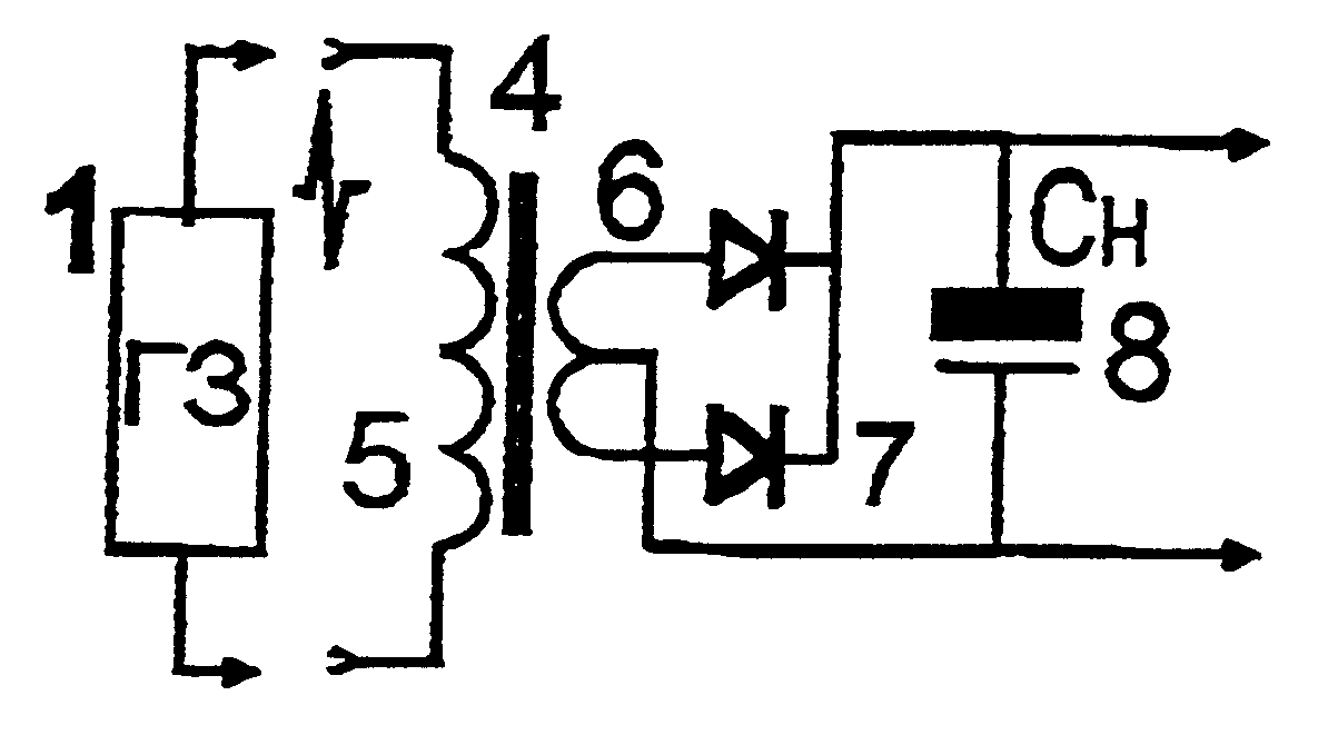
In one of the versions of embodiment of an apparatus for electronic systems power supply, a charge energy converter is implemented as a step-down transformer, the primary winding of which transformer is connected to output of an electric charge generator, and the secondary winding of which is connected through a rectifier to an electric charge storage. Such converter is efficient when a charge generator produces brief high-energy current pulses.
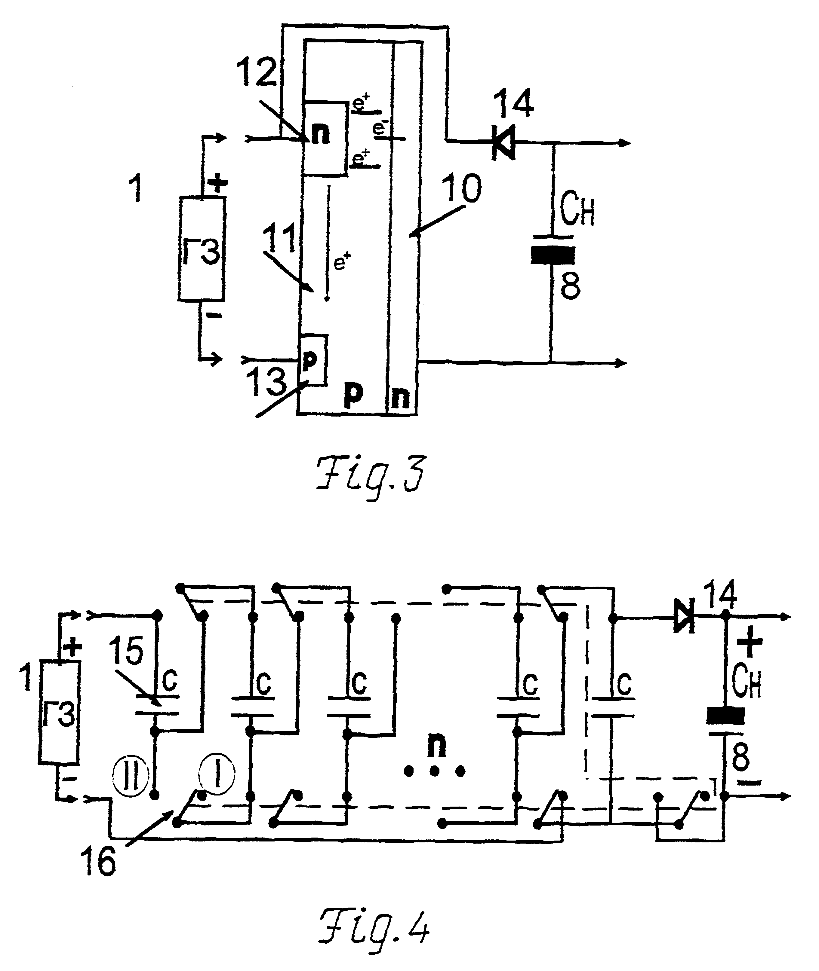
A charge energy converter can also be implemented as a plurality of capacitors provided with a switch device for switching capacitors from the series connection needed to store charges from a charge generator to subsequent parallel connection allowing to reduce the charges potential at output of a converter and in this way to use the whole charge stored in each individual capacitor to a more complete extent. In this version, the electric charges' energy produced by a charge generator is used most efficiently.

Problems solved by technology

A drawback of such apparatus is a limited service life of a galvanic source.
For a number of apparatuses these mechanical movements is a cumber, and the other drawback are relatively large dimensions and a high cost of such motor that restrict utilisation of power supply sources of such type.
However, this known teaching is not intended for storing the electric energy produced by a piezoelectric element and needed to procure the steady power supply for electronic systems.
However, the known method and apparatus are of a little efficiency for providing power supply for electronic systems.
It is not possible to use such high-voltage source for providing the direct power supply for low-voltage electronic systems, such as, for example, microelectronic circuits.

Method used


Image

  • Method of power supply for electronic systems and device therefor
  • Method of power supply for electronic systems and device therefor
  • Method of power supply for electronic systems and device therefor

Examples


Embodiment Construction

Referring to FIG. 1, an apparatus for electronic systems power supply comprises charge generator 1, output of which generator is connected to input of charge energy converter 2, and output of converter 2 is connected to input of charge storage 3, output of which storage is the output of the apparatus.

An electric charge storage can be implemented as an electric capacitor, as well as in the form of a more sophisticated system, comprising accumulating storages with galvanic or super-ionic elements.

According to FIG. 2a, an apparatus for electronic systems power supply, wherein a charge energy converter comprises transformer 4, the primary winding 5 of which transformer is the input of the converter, and its secondary winding 6, coupled to rectifier 7, forms the output of said converter, which output is coupled to storing capacitor 8 being the output element of said apparatus.

FIG. 2b shows an apparatus for electronic systems power supply, as implemented according to the arrangement shown...


PUM


Abstract

The invention relates to a method and apparatus that provide autonomous power supply by converting energy of sources of a non-electrical nature into the electric energy using charge generators. For such apparatuses, as charge generators can be used piezoelectric elements, triboelectric elements, as well as radioactive sources of charged particles that do not require periodic replacement of re-charging-in contradistinction to the convention sources of power supply, galvanic batteries. Charge generator (1), when activated, produces a portion of electric charges q having a high electric potential Uin, which portion is applied to the input of charge energy converter (2). The function of the converter (2) is to increase the initial value of charges q up to value of Q, with simultaneous reduction of their potential to Uout value, which less than Uin. For the purpose to store charges Q obtained as a result of the conversion, which charges Q are needed for the electronic systems power supply, electric charge storage (3) is positioned at the output of the apparatus.

Description

The invention relates to means of autonomous power supply for electronic systems, and in particular to a method and apparatus to provide power supply for microelectronic charges.PRIOR ARTEvolution of microelectronics has presently reached the point whereat for power supply of certain (e.g. CMOS) microelectronic circuits, that execute small volumes of computation, an extremely little amount of electric energy for their power supply is required. Therefore efforts are currently made to provide autonomous electric power supply for such microcircuits, using, for example, small-sized galvanic power sources integrated in their casing.A drawback of such apparatus is a limited service life of a galvanic source.In this connection, noteworthy are the attempts to abandon the short-life galvanic power supply sources and utilise small-sized apparatuses transforming energy of the sources of the non-electrical nature into the electric energy so that to obtain a small portion of electric charge that...

Claims


Application Information

Patent Timeline
IPC IPC(8): G21H1/00H02M3/07H02M3/16H02M3/18H02N1/00H02M3/04H02N1/04H02N11/00H02M3/00H02M11/00H01L41/113H02N2/18H10N30/30
CPCG21H1/00H02M3/00H02M3/07H02N11/002H02M11/00H02N1/04H02N2/181H02M3/18H02N3/00
Inventor NUNUPAROV, MARTYN SERGEEVICHMASLENNIKOV, NIKOLAI MIKHAILOVICH
Owner NUNUPAROV MARTYN SERGEEVICH
Learn More