

Double heat exchanger
- Summary
- Abstract
- Description
- Claims
- Application Information
AI Technical Summary
Benefits of technology
Problems solved by technology
Method used
Image

Examples
first embodiment
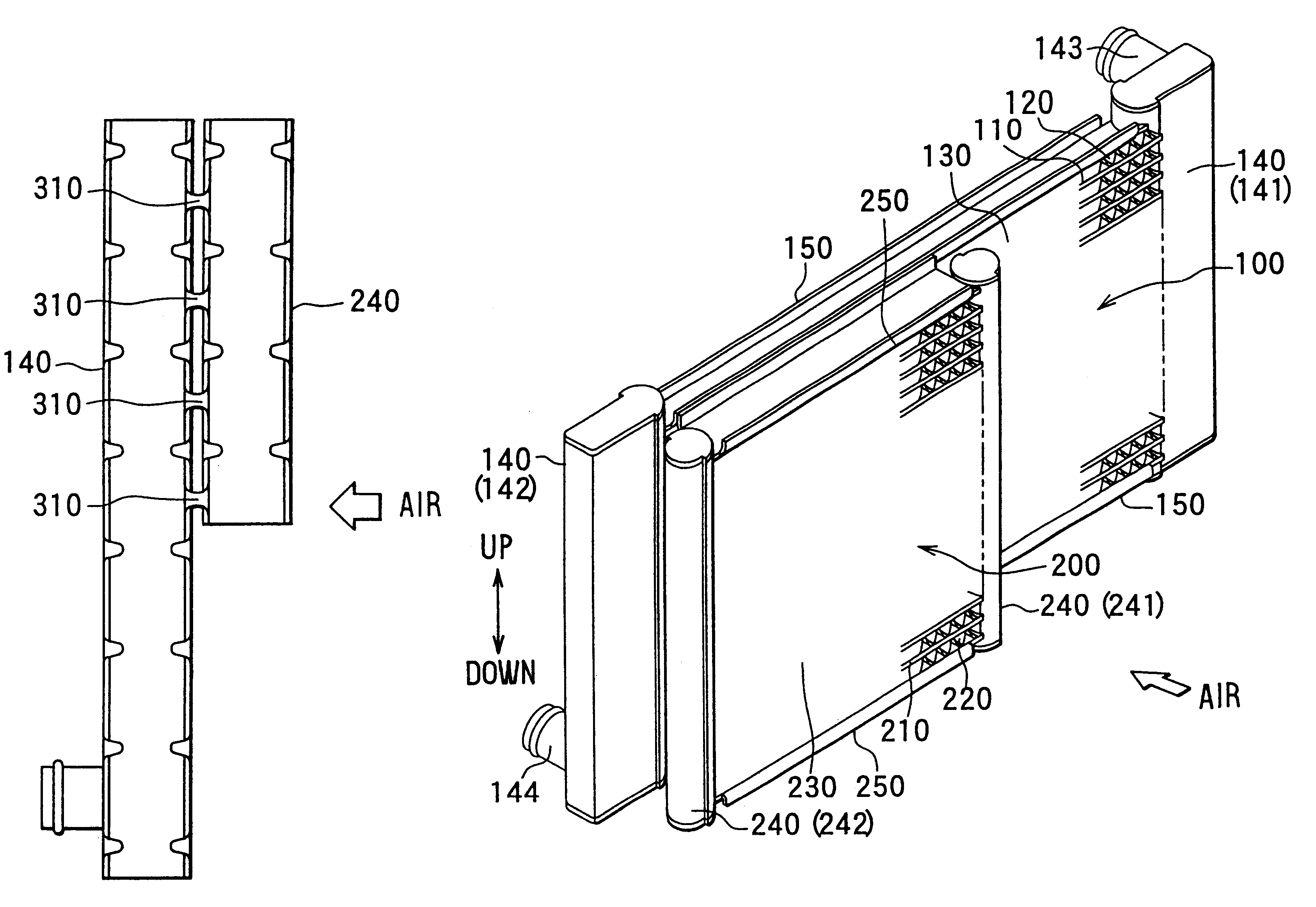
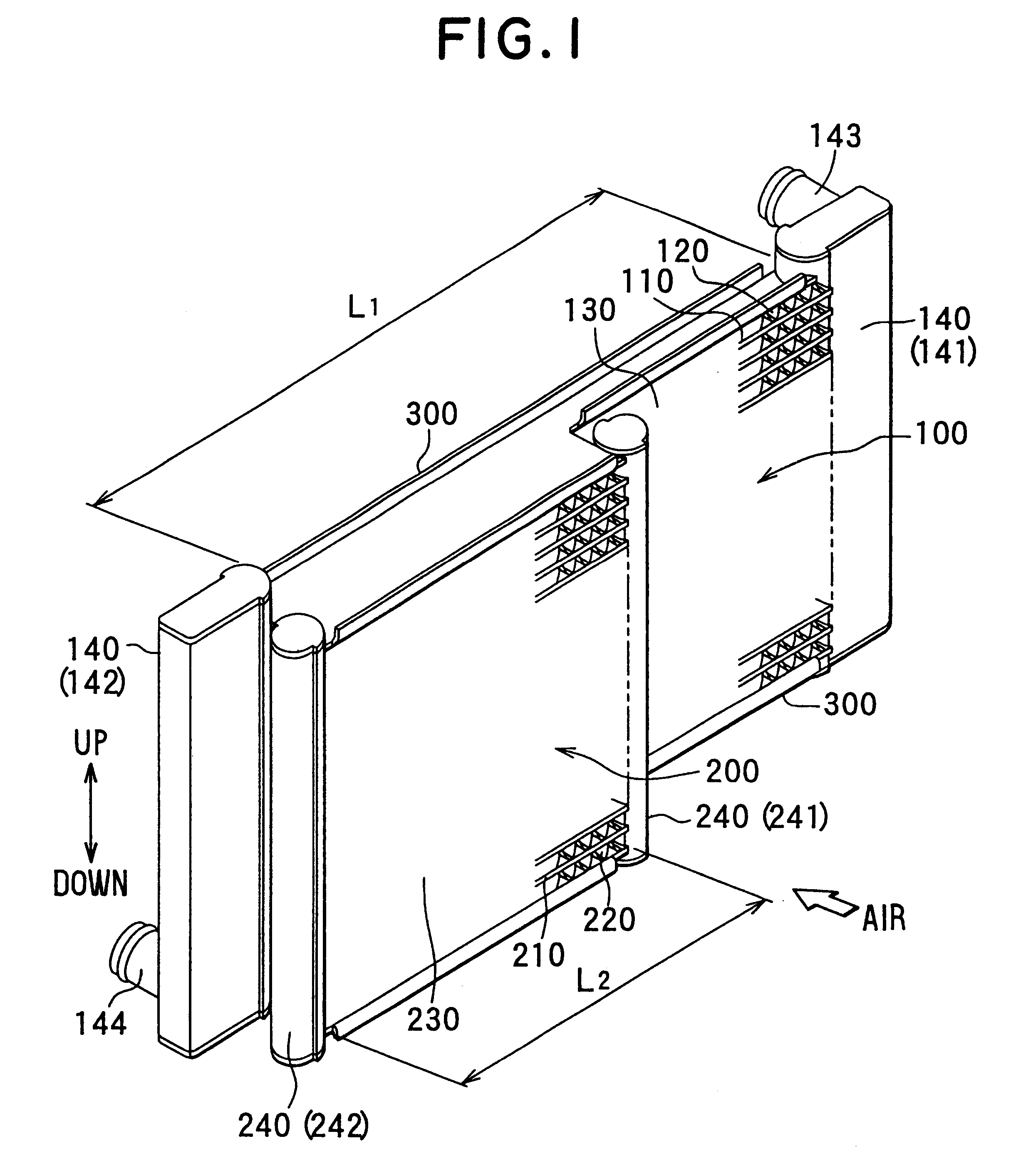
In the first embodiment, each longitudinal dimension L2 of the condenser tubes 210 between the first and second condenser header tanks 241, 242 is set to be smaller than each longitudinal dimension L1 of the radiator tubes 110 between the first and second radiator header tanks 141, 142, so that a core area of the condenser core portion 230 is made smaller than a core area of the radiator core portion 130. Here, the core area of the condenser core portion 230 is a reflection area of the condenser core portion 230 on a surface perpendicular to the air-flowing direction. Similarly, the core area of the radiator core portion 130 is a reflection area of the radiator core portion 130 on a surface perpendicular to the air-flowing direction.
On both side ends of both the core portions 130, 230, side plates 300 for reinforcing both the core portions 130, 220 are provided. The side plates 300 are disposed to extend in a direction parallel to the flat tubes 110, 210. In the first embodiment, th...
fourth embodiment
A fourth preferred embodiment of the present invention will be now described with reference to FIG. 6. As shown in FIG. 6, a distance between centers of the adjacent radiator tubes 110, i.e., a pitch P1 between adjacent radiator tubes 110, is set to be equal to a distance between centers of the adjacent condenser tubes 210, i.e., a pitch P2 between adjacent radiator tubes 110. However, in the fourth embodiment, each tube thickness L3 (i.e., minor-diameter dimension) of the radiator tubes 110 is made smaller than each tube thickness L4 (i.e., minor-diameter dimension) of the condenser tubes 210. Here, the tube thickness L3 of the radiator tubes 110 is a dimension of each radiator tube 110, parallel to the tank longitudinal direction of the radiator tank portion 140. Similarly, the tube thickness L4 of the condenser tubes 210 is a dimension of each condenser tube 210, parallel to the tank longitudinal direction of the condenser tank portion 240.
That is, in the fourth embodiment of the...
sixth embodiment
Further, in the present invention, a recess portion 331 for reducing a heat-transmitting area is provided in the condenser side plate 331 to restrict heat from being transmitted from the radiator 100 to the condenser 200. Therefore, the recess portion 331 provided in the condenser side plate 331 prevents heat-exchanging capacity of the condenser 200 from being greatly reduced.
A seventh preferred embodiment of the present invention will be now described with reference to FIGS. 11. In the seventh embodiment, similarly to the fifth embodiment, the strength of the condenser 200 and the connection strength between the core portions 130, 230 are improved in the double heat exchanger described in the second embodiment.
As shown in FIG. 11, in the seventh embodiment, the longitudinal dimension h4 of the condenser tank portion 240 is set to be larger than the core height hc2 of the condenser core portion 230. Further, both longitudinal ends of the condenser tank portion 240 are bonded and bra...
PUM
 Abstract
Description
Claims
Application Information