Gas burners for heating a gas flowing in a duct

a technology of gas burners and ducts, which is applied in the direction of combustion types, combustion processes, lighting and heating apparatus, etc., to achieve the effect of preserving good flame stability

Inactive Publication Date: 2002-06-25
ENTERPRISE GENE DE CHAUFFAGE IND PILLARD
View PDF11 Cites 4 Cited by
  • Summary
  • Abstract
  • Description
  • Claims
  • Application Information

AI Technical Summary

Benefits of technology

The problem posed is thus to be able to make an "in-stream" burner operate while complying with the above values set by regulations and simultaneously preserving good flame stability.
Such a tube injects a portion of the fuel gas, for example at a distance of at least 100 millimeters (mm) downstream from the other orifices not fitted with tubes, thereby enabling the injection of the gas to be staged and enabling the resulting combustion flames to be staged, thus reducing the percentage of nitrogen oxides, NOx, that is produced. The main flame obtained by this staged injection, i.e. the flame which is further from the deflector stabilizer, is thus more aerated. Combustion thus takes place with a greater excess of air and therefor at a lower temperature, thereby producing a great reduction in the formation of those nitrogen oxides that are essentially of thermal origin. The greater the staging, the greater the extent to which nitrogen oxides are reduced.
In addition, in order to be able to further improve this staging effect by reducing the primary flow rate, it is possible to conserve the stability of the main or "secondary" flame since it achieves fuel gas staging with only 10.degree. of the gas in the primary orifices thus not having a tube. For this purpose, in accordance with the invention, it is possible to introduce a portion of the oxidizing gas at the root of the secondary flame. In addition to increasing the stability of the flame during turbine gas operation, this technique also has the advantage of reducing nitrogen oxide NO contained in the gas by the so-called "reburning" effect (where NO is transformed into N.sub.2 by chemical reduction coming from the CH.sup.+ radicals present at the root of the flame). It is also possible to add at least one obstacle placed facing at least one gas jet ejected by one of the holes that is not extended by a tube, thereby encouraging them to expand and enlarge the pilot flame, which is also referred to as the "primary" flame, so as to impart better efficiency thereto.
The result are novel gas burners for heating a gas flowing in a duct. The novel gas burners include improvements to presently known burners since they solve the same problem, which is that of complying with the values set by regulations concerning nitrogen oxide NOx and carbon oxide CO emissions, while ensuring good flame stability and an aeration rate that is practically constant in the air-and-fuel mixture regardless of variations in the fuel flow rate and / or in the speed of the gas to be heated.

Problems solved by technology

The problem posed is thus to be able to make an "in-stream" burner operate while complying with the above values set by regulations and simultaneously preserving good flame stability.

Method used


Image

  • Gas burners for heating a gas flowing in a duct
  • Gas burners for heating a gas flowing in a duct
  • Gas burners for heating a gas flowing in a duct

Examples


Embodiment Construction

)

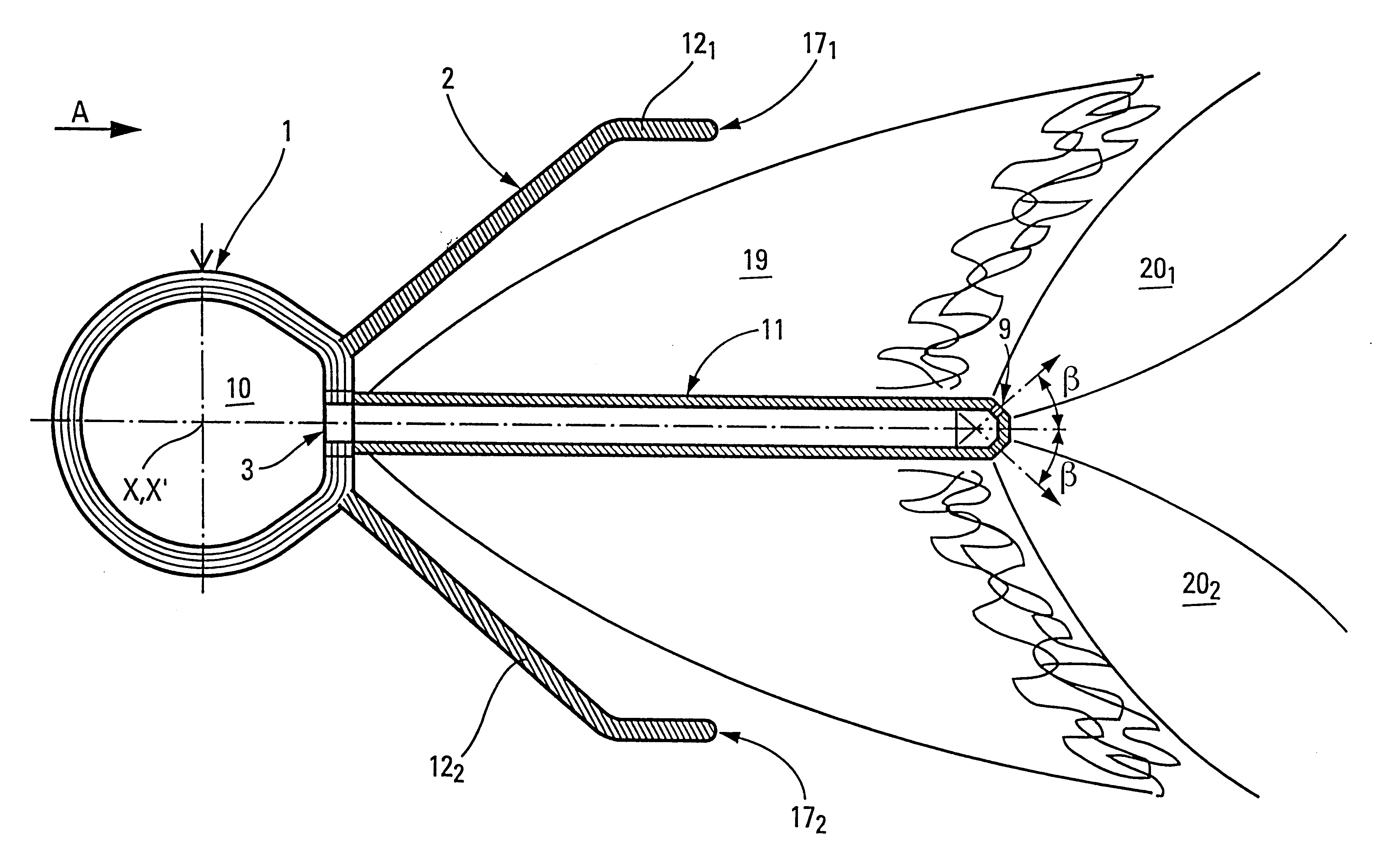
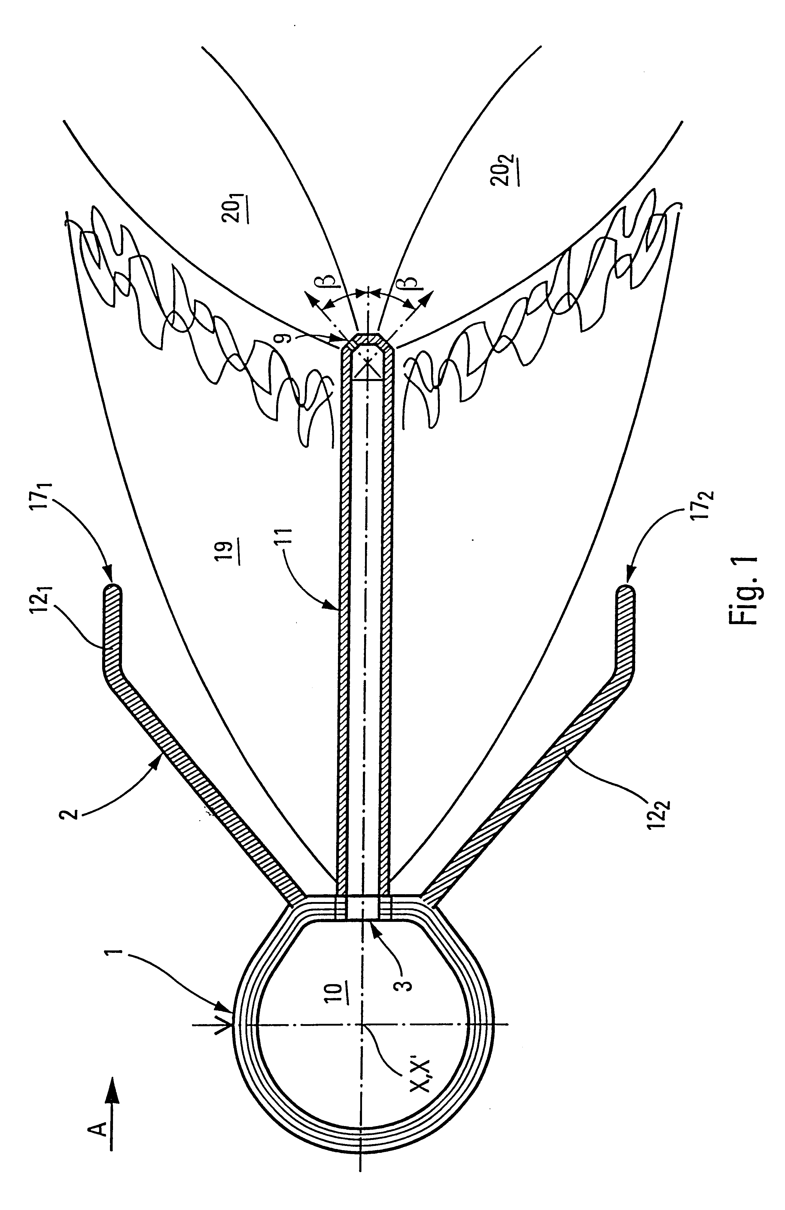
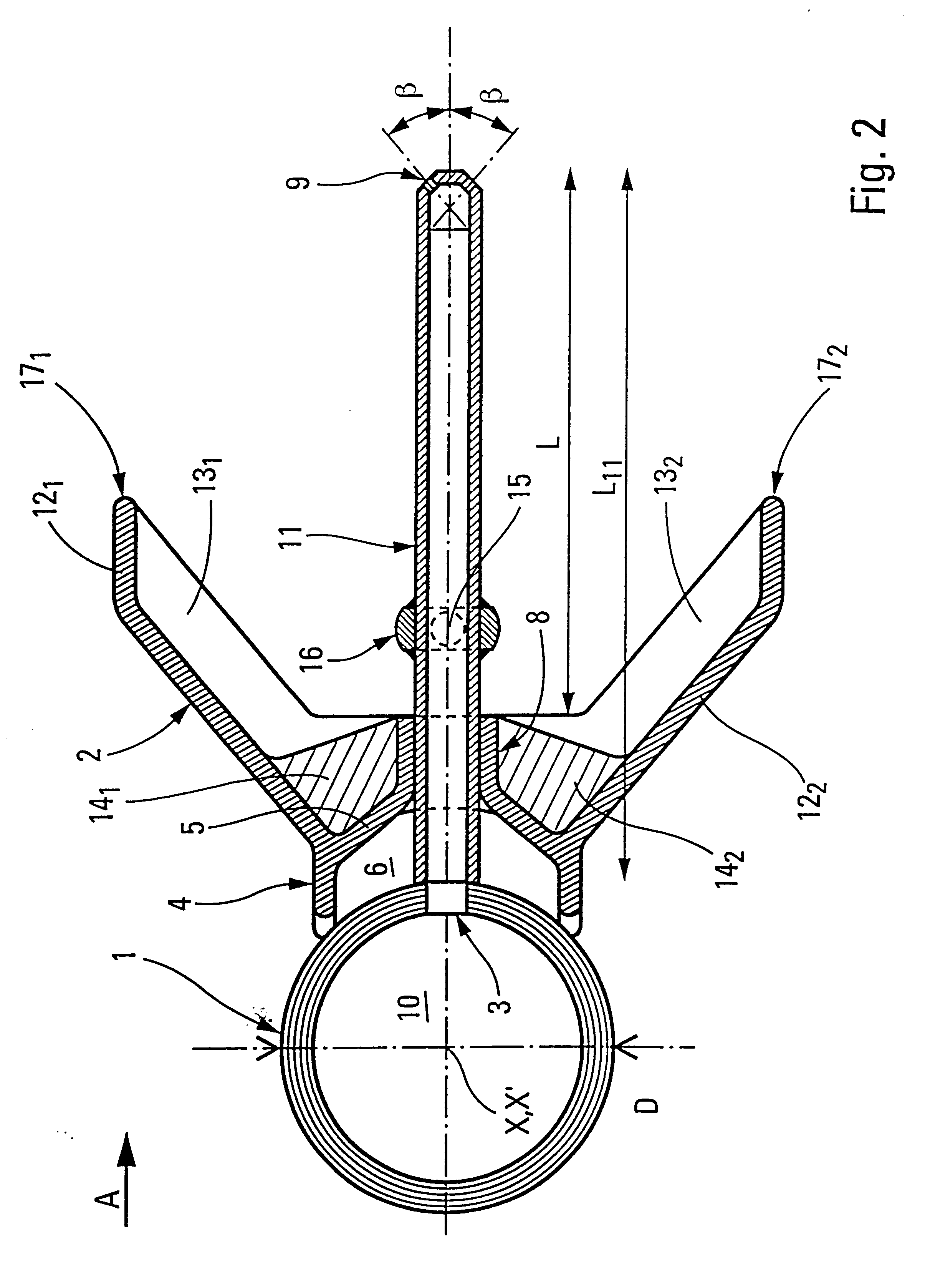
The invention relates to a type of burner to be placed in a duct to heat a gas flowing along the duct. The burner comprises a pipe 1 of axis XX' suitable for extending transversely across the flow direction A of the gas. The pipe can be circular in section and have a diameter D, as shown in FIG. 2, but it could equally well be arbitrary in section, for example, having a section as shown in FIG. 1. It can carry a plurality of burner blocks placed side by side to make up a burner rail.

The pipe 1 is fed with fuel gas 10 and is pierced by at least two holes 3 per burner block with the two holes being in alignment on a common generator line 18 which is parallel to the axis XX' of the tube. The pipe 1 carries a flame stabilizer 2 formed by two deflector-forming fins 12 diverging on either side of the generator line 18.

In the embodiments shown in FIGS. 2 to 5, the deflector stabilizer 2 can have walls 13.sub.1, 13.sub.2, forming reinforcing ribs at the ends, along the direction of the axi...


PUM


Abstract

The technical field of the invention is that of making "in-stream" burners which are placed directly inside a duct carrying a flow of gas, with the burners serving to heat the gas and being placed as burner rails that are generally made up of individual blocks. Such burners comprising a pipe on an axis XX' and suitable for extending transversely across the flow direction of the gas, the pipe being fed with a fuel gas and being pierced by at least two holes in alignment on a common generator line, the burner also having a flame stabilizer formed by two deflector-forming fins diverging on either side of the generator line. According to the invention, at least one of the holes is extended by a tube extending beyond the outer edges of the fins and pierced by at least one fuel gas ejection orifice at its distal end.

Description

The present invention relates to an improvement to gas burners for heating a gas flowing in a duct.The technical field is making "in-stream" burners which are placed directly inside a gas flow duct, which burners are disposed as a rail generally made up of individual blocks and extending transversely across the gas flow direction.In the present description, the term "burner" is used both to cover a rail made up of a plurality of individual blocks, and an individual block on its own.The main applications of the invention are in heating turbine gas in co-generator installations. A "post-combustion" burner serves to improve the overall efficiency of the installation, to modulate the production of steam as a function of requirements, and, as a by-product, also serves to maintain such production in the event of the gas turbine stopping. Under such circumstances, a fan sucks in ambient air and delivers the oxygen required by the burners instead of and as a replacement for the exhaust gas ...

Claims


Application Information

Patent Timeline
Patent Type & Authority Patents(United States)
IPC IPC(8): F23G7/06F23D14/74F23D14/00F23D14/20F23C6/04F23C6/00F23D14/72
CPCF23C6/047F23C2201/20F23C2201/30F23D14/20F23D14/74F23D2900/21003F23G7/065
Inventor BURY, FREDERIC
Owner ENTERPRISE GENE DE CHAUFFAGE IND PILLARD
Why Eureka
Try Eureka