Apparatus for testing various structural parameters of an electro-magnetic radiation barrier

a radiation barrier and apparatus technology, applied in the direction of resistance/reactance/impedence, material magnetic variables, instruments, etc., can solve the problems of reliability and/or performance, interference with the proper operation of television sets, radios and other electronic devices, and it is rarely practical to perfectly enclose the electro-magnetic radiation source. , to achieve the effect of improving the design of electro-magnetic radiation suppression shields and improving the control of electro-magnetic interferen

Inactive Publication Date: 2002-06-25
IBM CORP
View PDF7 Cites 18 Cited by
  • Summary
  • Abstract
  • Description
  • Claims
  • Application Information

AI Technical Summary

Benefits of technology

It is an object of the invention to improve the design of electro-magnetic radiation suppression shields, thereby improving control of electro-magnetic interference.

Problems solved by technology

Electro-magnetic interference can cause interference with the proper operation of television sets, radios and other electronic devices; moreover, it can interfere with computers and servers wherein the foreign electro-magnetic interference affects the reliability and / or performance of computer processors in such systems.
However, it is seldom practical to perfectly enclose the electro-magnetic radiation source inasmuch as the electro-magnetic radiation sources are commonly mounted on circuit boards which may not be practically enclosed totally.
Additionally, the electro-magnetic radiation source may generate sufficient heat during its operation that the heat must be dissipated in order to prevent the electronic devices from overheating and resulting in circuit or component failure.
The least expensive cooling technique is the passage of cooling air through the electro-magnetic radiation suppression shield.
The electrically conductive electro-magnetic radiation suppression plate placed in an air cooling opening in the electro-magnetic radiation suppression shield greatly reduces the escaping electro-magnetic radiation and reduces its effect on the remaining escaping electro-magnetic radiation which then becomes a lower level electro-magnetic interference.
This process can be and is repeated many times at a substantial expense before determination of an acceptable level of electro-magnetic interference and the specific design of the electro-magnetic radiation suppression enclosure.
The design and verification process to suppress and control electro-magnetic radiation can be laborious and time consuming as well as expensive.

Method used


Image

  • Apparatus for testing various structural parameters of an electro-magnetic radiation barrier
  • Apparatus for testing various structural parameters of an electro-magnetic radiation barrier
  • Apparatus for testing various structural parameters of an electro-magnetic radiation barrier

Examples


Embodiment Construction

AS CONTEMPLATED BY THE INVENTORS

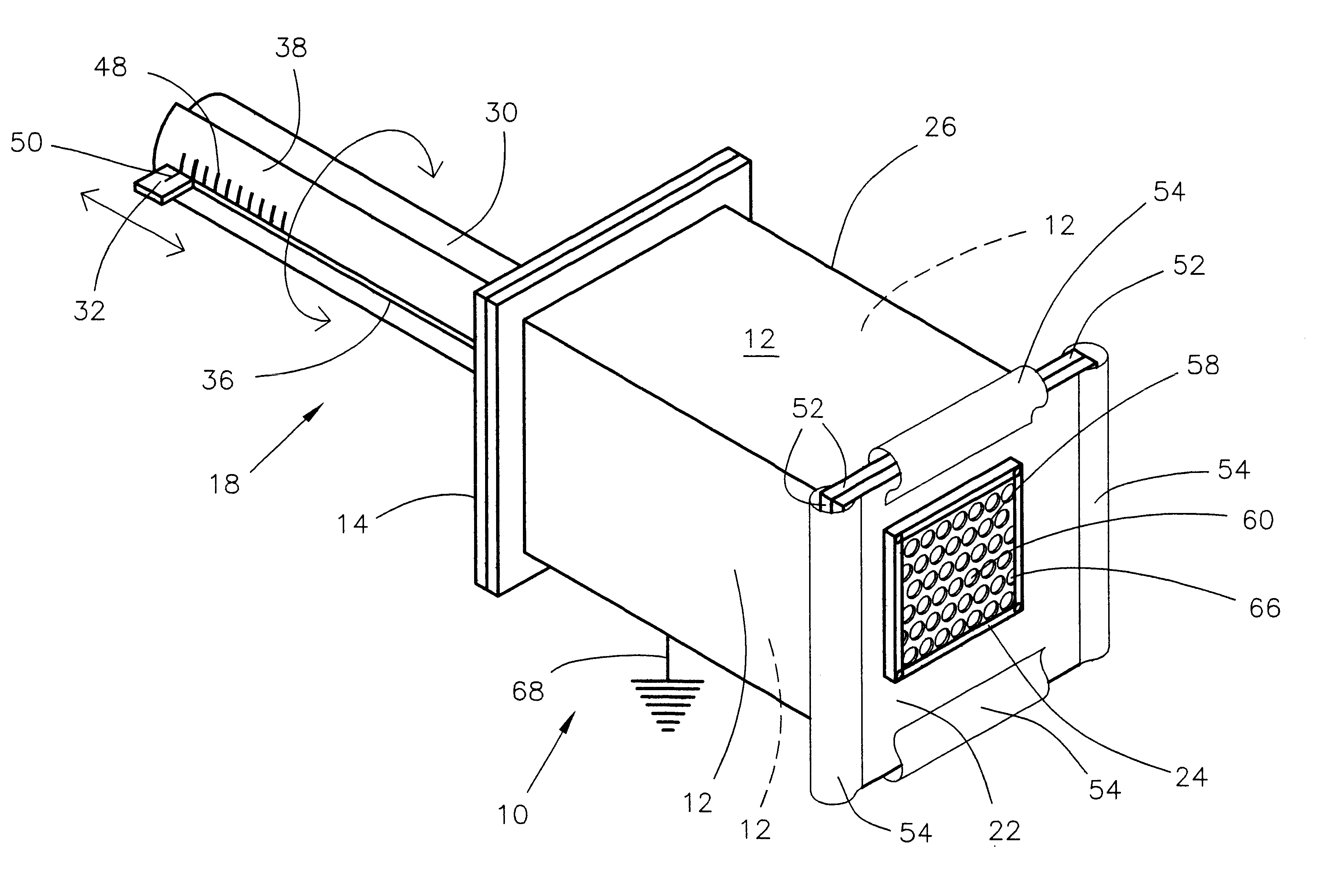
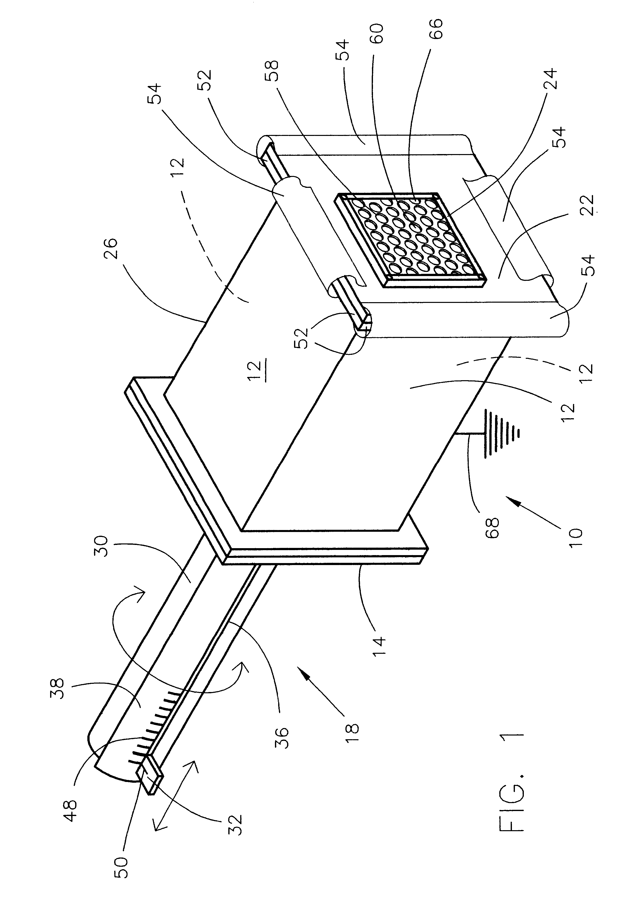
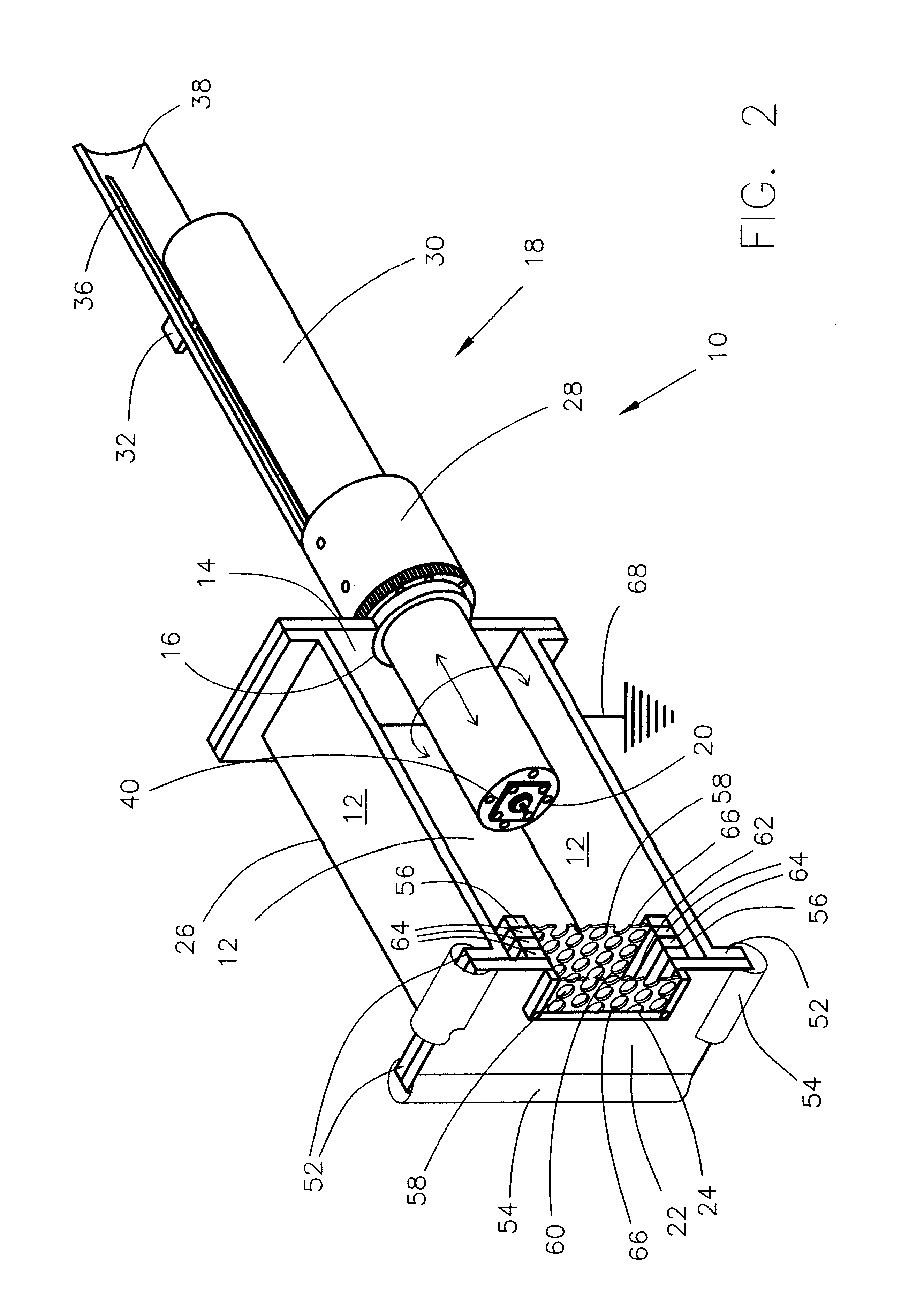
The assembled electro-magnetic radiation suppression test apparatus 10 is variously illustrated in FIGS. 1 and 2. The body of the electro-magnetic radiation suppression test apparatus 10 is typically and preferably a metal box having sides 12 forming a rectangular structure 26. The rear of the hollow rectangular structure 26 is preferably closed by a rear wall 14 having an aperture 16 through which an emitter support 18 extends.

Closing the front end of rectangular structure 26 is a plate 22 which has an opening 24 formed therein. Opening 24 is formed in the shape and of the dimensions of a specific air flow opening being considered for use in an electronic apparatus (such as a computer, server or other electronic device) which has a processor or other source of electro-magnetic radiation, emitter 20. End panel 22 or plate 22 may be and preferably is mounted temporarily on the rectangular structure 26 for ease in testing. Additionally, if varied openin...


PUM

PropertyMeasurementUnit
electrically grounded conductiveaaaaaaaaaa
electro-magnetic radiationaaaaaaaaaa
electro-magneticaaaaaaaaaa

Abstract

The design of an electro-magnetic radiation suppression shield and cooling housing for a computer, server or other electronic device having a computer processor may be greatly enhanced and expedited by a test apparatus that permits the placement of electro-magnetic radiation suppression plates at differing locations, spacings and alignments, which allows a variance in positioning the electro-magnetic radiation source. The test apparatus not only has an air flow cooling opening in which an electro-magnetic radiation suppression panel forms cooling air flow holes but also a fixture for disposing a second similar electromagnetic radiation suppression panel at a distance from the first electro-magnetic radiation suppression panel. Each of the panels may be substituted to test various designs. The test apparatus further is provided with a telescoping support projecting into the interior cavity so that the electromagnetic radiation source may be moved about in the interior and thus simulate a large number of positions and conditions. The test apparatus provides a greatly enhanced tool in the trial and error approach to electro-magnetic radiation control.

Description

This invention relates to the design of suppression devices for controlling the electro-magnetic radiation which is radiated from electronic devices such as computer processors and, more specifically, to the testing of design parameters of such devices by providing readily changeable structural parameters of such an electro-magnetic radiation suppression device.United States government standards require control of electro-magnetic interference for all devices such as computers, servers, and other electronic devices which may emit electro-magnetic radiation from their electronic components. Electro-magnetic interference is defined as the adverse affects of electro-magnetic radiation emitted in proximity to an electro-magnetic radiation sensitive device.Electro-magnetic interference can be caused by electro-magnetic radiation which has escaped from a device within which it is generated. Electro-magnetic interference can cause interference with the proper operation of television sets, ...

Claims


Application Information

Patent Timeline
Patent Type & Authority Patents(United States)
IPC IPC(8): H05K9/00
CPCH05K9/0069
Inventor GILLILAND, DON ALANHOLAHAN, MAURICE FRANCISPEACOCK, JAMES LARRY
Owner IBM CORP
Why Eureka
Try Eureka