Color converting method, density-gradient correction method and color printer using the same

a color printer and density gradient technology, applied in the field of color conversion methods and density gradient correction methods of printers, can solve the problems of insufficient margin for continuously reproducing the gradient in secondary or higher colors, user incorrectly determining that original data has an error, and inability to check

Inactive Publication Date: 2002-06-25
FUJIFILM HLDG CORP +1
View PDF9 Cites 20 Cited by
  • Summary
  • Abstract
  • Description
  • Claims
  • Application Information

AI Technical Summary

Benefits of technology

The foregoing method was adapted to a color printer according to the following embodiment so as to confirm the effect of the present invention.

Problems solved by technology

The two conventional methods have the following problems.
In this case, there arises a problem in that a user incorrectly determines that original data has an error if mixture of cyan (C) is detected when the user confirms that data is composed of only magenta (M) and yellow (Y) by using a magnifier.
(1) In a case of the halftone dot gradient, whether the gradient is solid (that is, a shadow having a gradient of 100%) or 99% can easily be determined by using a magnifier. That is, white missing in a solid image can easily be detected. When a user looks the image to confirm that the image is a solid image by using a magnifier, the user detects some white missing portions. In this case, there arises a problem in that the user misunderstands that original data has an error and thus checking cannot be performed.
(2) If original data is black data, solid characters are frequently used and thicknesses must strictly be correct. If an end of a character becomes faint, it appears that a thin character has been formed. To prevent this, a gradient of 99% is insufficient. In this case, the gradient must reliably be made to be 100%.
(3) The above-mentioned problems must always be solved even if the sensitivity of the material and the machine is changed. Therefore, density calibration for compensating the difference in the sensitivity of the material and the machine must be performed.
In this case, there arises a problem in that the margin for continuously reproducing the gradient in the secondary or higher color becomes insufficient for the highlight portions when the density calibration of the primary color is performed.
In this case, a dot is undesirably added to even a non-image portion if the color is secondary or higher color and a highlight image is formed.

Method used


Image

  • Color converting method, density-gradient correction method and color printer using the same
  • Color converting method, density-gradient correction method and color printer using the same
  • Color converting method, density-gradient correction method and color printer using the same

Examples


Embodiment Construction

Condition

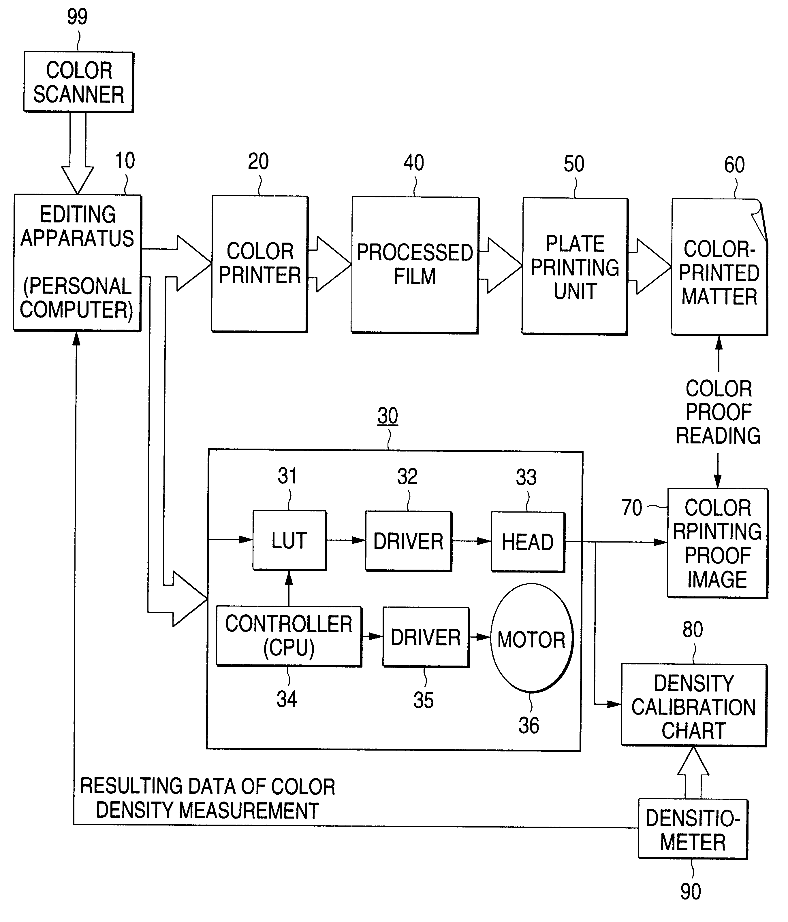
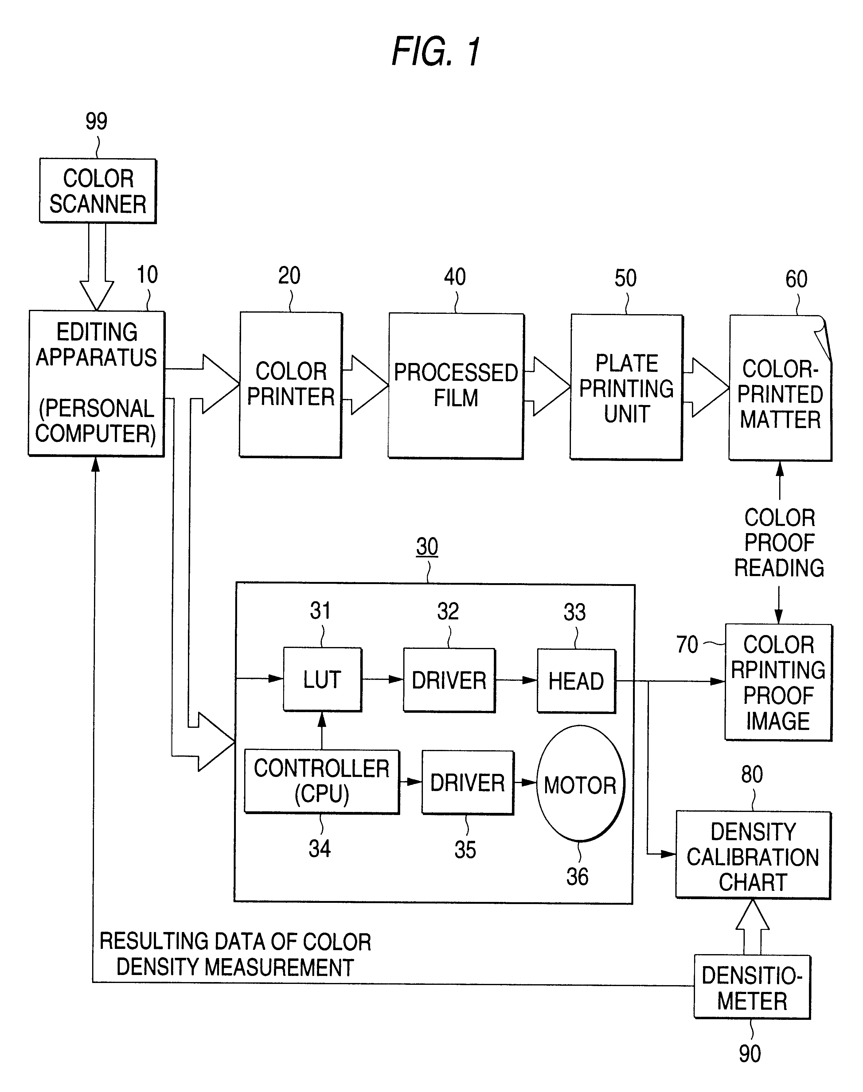
Printer: Digital Color Proof FIRST PROOF Printer manufactured by Fuji Film

Laminator: Digital Color Proof FIRST PROOF Laminator manufactured by Fuji Film

Receiving Sheet: Receiver Sheet A3W for Digital Color Proof FIRST PROOF manufactured by Fuji Photo Film Co., Ltd.

Thermal Transfer Ribbon: Proof Ribbon Adjacent for Digital Color Proof FIRST PROOF manufactured by Fuji Photo Film Co., Ltd.

Main Paper: Tokubishi Art Paper

The receiving sheet and the thermal transfer ribbon were those for the thin-layer thermal transfer process. The material adapted to the foregoing method incorporates a coloring material layer having a thickness of 1 .mu.m or smaller, preferably about 0.3 .mu.m or smaller. Since the thickness is very small, a higher resolution can be obtained as compared with the other thermal transfer method. Therefore, fine dots can stably be formed.

Other purposes, as well as the thermal transfer method, the method according to the present invention is effective for electronic ...


PUM

PropertyMeasurementUnit
thicknessaaaaaaaaaa
thicknessaaaaaaaaaa
energyaaaaaaaaaa

Abstract

A method of color conversion includes preserving a 0% density for a particular color in the pre-conversion state to maintain a 0% density after conversion is provided via a translation table. Density gradation methods include a gradient value structure such that the highlight and shadow regions of the density are more finely represented in comparison to non-highlight and non-shadow regions. A further density correction method includes supplying an amount of energy to a non-image area when printing using a first color, wherein the amount of energy will not produce a dot in the non-image area upon application of a second color. A printer may employ one or more of the above methods in the form of a translation table or a density correction patch.

Description

BACKGROUND OF INVENTIONThe present invention relates to a color conversion method and a density gradient correction method for a printer for mainly producing a color proof for forming a color image and a printer capable of performing the methodsWhen a color proof is produced by using a color conversion (hereinafter called "color matching") technology for matching a color print to printed matter, a color matching method similar to a conventional method is employed. That is, yellow (Y), magenta (M), cyan (C) and black (K) data items are first converted into data of chromaticity, and then converted into C, M, Y and K data peculiar to the printing system by using a translation table. The above-mentioned method is a known and marketed color matching method as "Color Sync" (trade name).A density calibration technology for correcting the sensitivity difference of a material and a machine is disclosed in Japanese Patent Application No. Hei. 9-126108 applied by the applicant of the present i...

Claims


Application Information

Patent Timeline
Patent Type & Authority Patents(United States)
IPC IPC(8): B41J2/36H04N1/60B41J2/52B41J2/525G03F3/10H04N1/407
CPCB41J2/36H04N1/603H04N1/6008
Inventor SAWANO, MITSURUSHIRAI, SHU
Owner FUJIFILM HLDG CORP
Why Eureka
Try Eureka