Power inverter

a technology of power inverter and sealing portion, which is applied in the direction of electrical apparatus construction details, solid-state devices, semiconductor devices, etc., can solve the problems of difficult maintenance of such a power inverter, liquid may leak to the circuit substrate side from the degraded sealed portions, etc., to achieve excellent cooling performance, prevent leakage, and reduce the size of the apparatus

Inactive Publication Date: 2002-07-02
HITACHI LTD
View PDF3 Cites 169 Cited by
  • Summary
  • Abstract
  • Description
  • Claims
  • Application Information

AI Technical Summary

Benefits of technology

It is an object of the present invention to provide a power inverter that has an excellent cooling performance, prevents leakage, and allows size reduction of the apparatus and easy maintenance.

Problems solved by technology

Thus, disadvantageously, the individual bolts must be sealed and if the sealed portions of the bolts are degraded, the liquid may leak to the circuit substrate side from the degraded sealed portions.
In this case, however, if the circuit is to be replaced due to defect thereof, it must be disassembled and dismantled together with the cooling case (heat sink).
Thus, a new problem arises particularly with a power inverter for a hybrid vehicle using one enclosure to house a plurality of circuits; that is, maintenance for such a power inverter is difficult.

Method used


Image

  • Power inverter
  • Power inverter
  • Power inverter

Examples


first embodiment

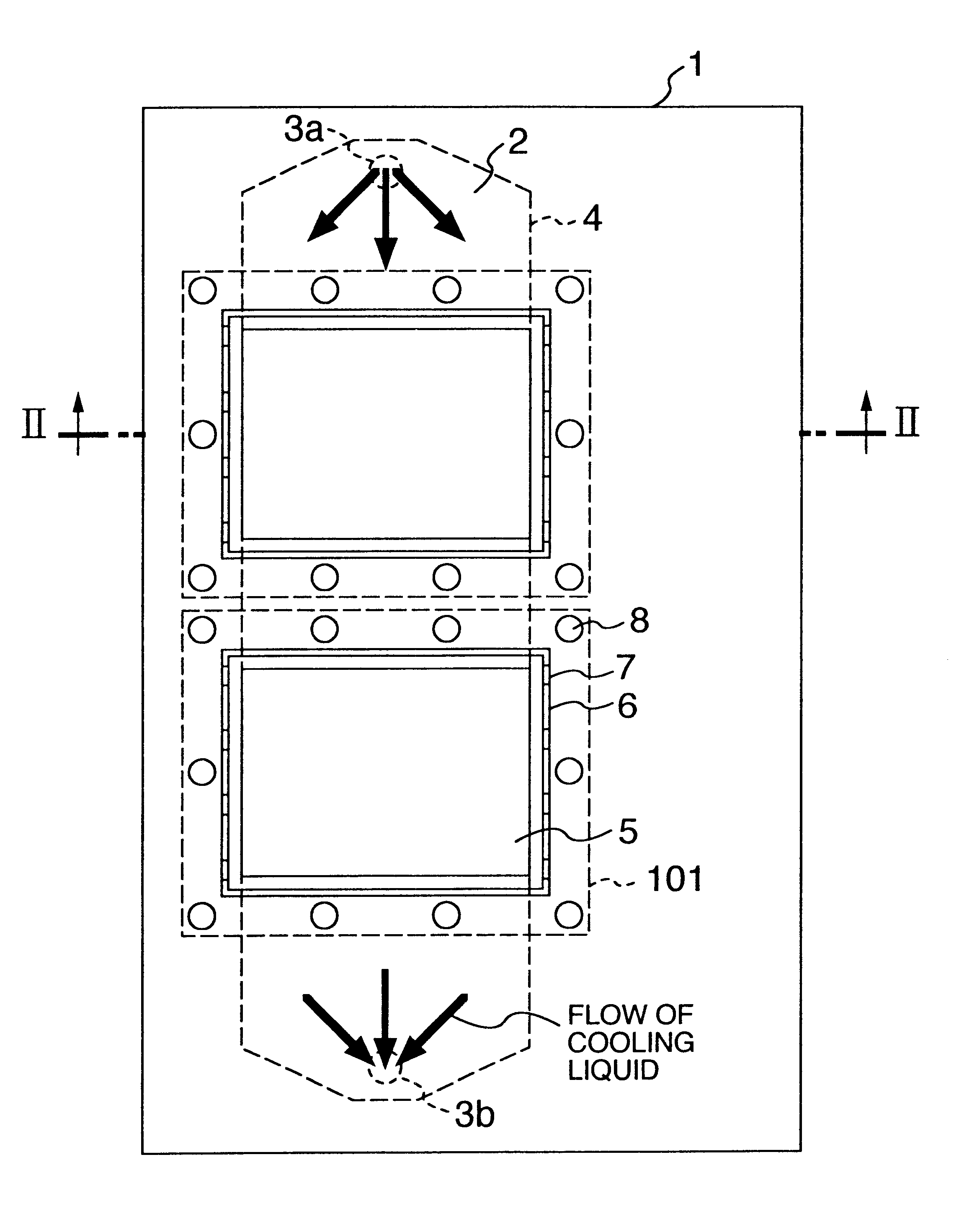
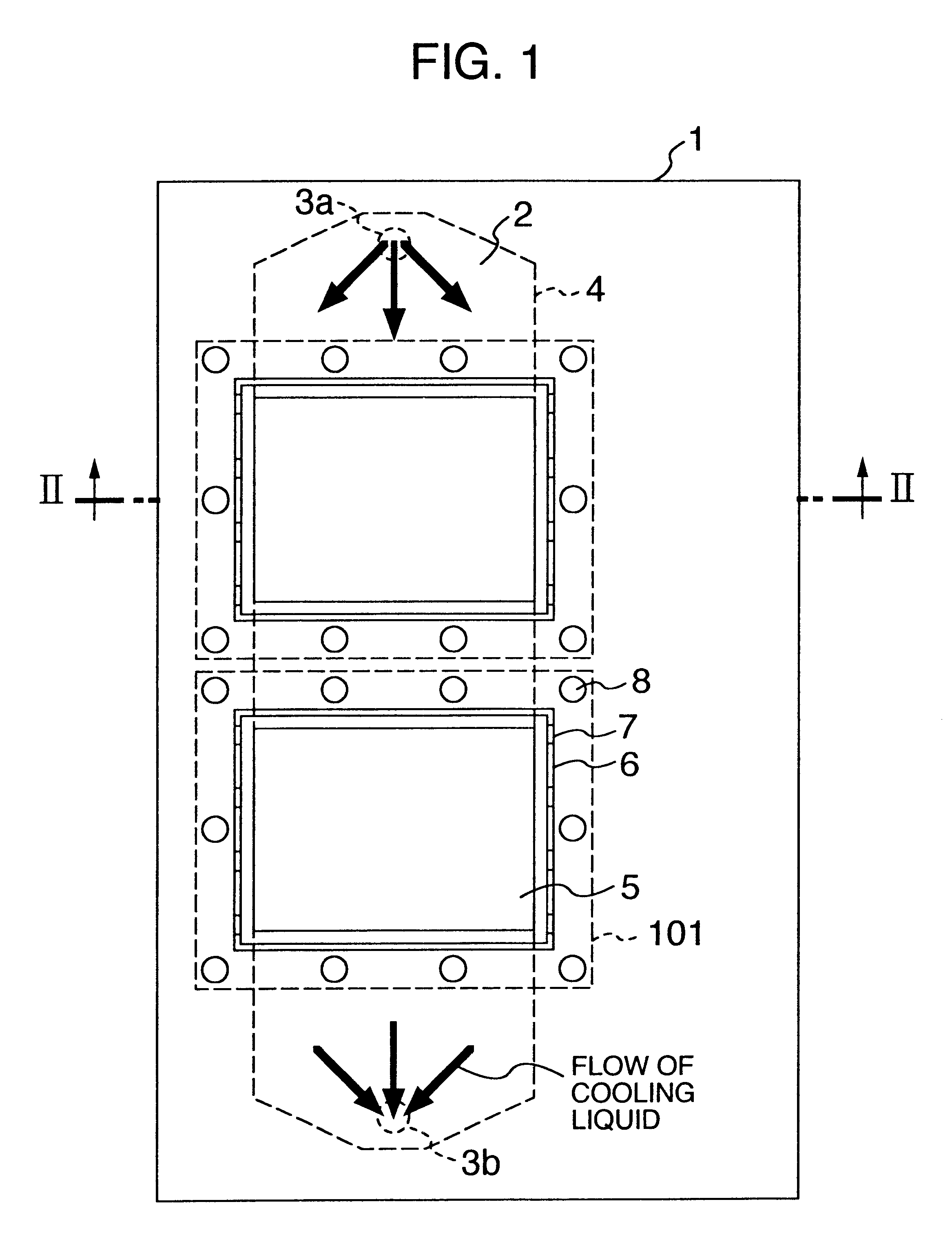
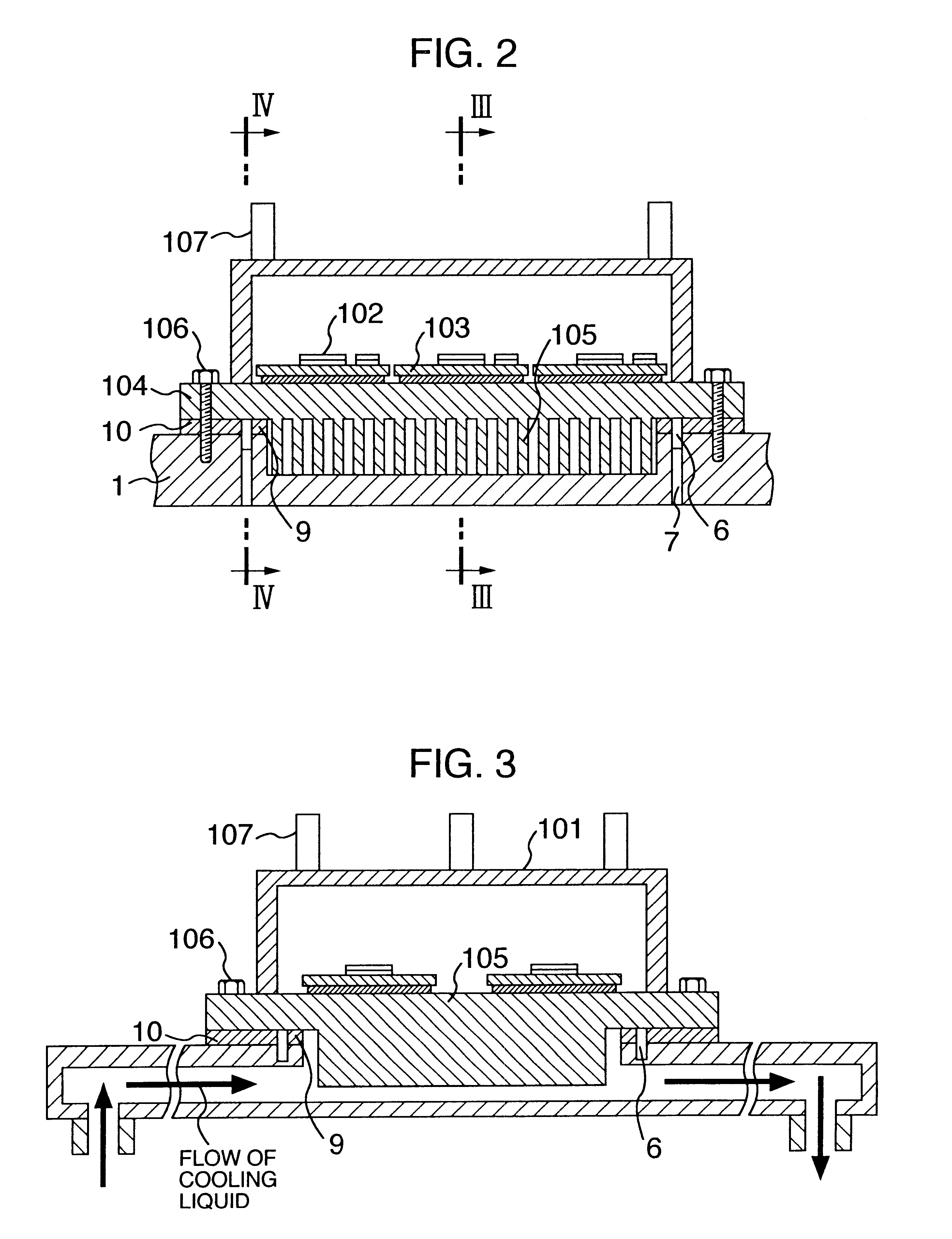
the power inverter of the present invention will be described with reference to FIGS. 1 to 4. FIG. 1 is a view showing a configuration of a cooling section of a power inverter module according to a first embodiment of the present invention. FIG. 2 is a sectional view taken along a line II--II in FIG. 1. FIG. 3 is a sectional view taken along a line III--III in FIG. 2. FIG. 4 is a sectional view taken along a line IV--IV in FIG. 2.

This embodiment shows a power inverter for a hybrid vehicle and shows an example of a case where two respectively independent inverter circuits are mounted to control two revolving electric apparatus. These drawings principally show semiconductor modules and heat sinks (cooling cases or substrates) for cooling the semiconductor modules and omit description of other electric parts such as a capacitor and a microcomputer control circuit, wiring, and parts. electric parts such as a capacitor and a microcomputer control circuit, wiring, and others.

First, the co...

second embodiment

Next, the power inverter of the present invention will be described with reference to FIG. 5. FIG. 5 is a sectional view of cooling structure for the semiconductor modules.

This embodiment differs from the first embodiment in that clamping bolts 106b are provided in the pressure contact areas of the first seal portion 9. It should be noted that for the clamping bolts in the first seal portion 9, through-holes are formed in the heat sink 1, while internal thread holes are formed in the radiating plate 104 but processed so as not to penetrate through the substrate into the case for the semiconductor modules. These bolts chiefly serve to obtain an appropriate surface pressure in the pressure contact areas of the first seal portion and to improve the distribution of surface pressure, thereby further improving the sealing performance. In addition, since the internal thread holes do not penetrate the radiating plate 104, the possibility that the liquid will leak into the semiconductor modu...

third embodiment

the power inverter of the present invention will be described with reference to FIG. 6. FIG. 6 is a sectional view of cooling structure for the semiconductor module.

This embodiment differs from the first embodiment in that leakage sensors 11 are provided in each groove 6. The leakage sensors 11 detect leakage to issue, for example, an alarm signal to a driver or stop the operation of the power inverter. Also in this case, in order to prevent the pressure of the liquid from being applied to the second seal portion, the groove 6 also has the holes 7 discretely provided at the bottom of the grooves 6, which are in communication with an atmosphere outside the apparatus. With this configuration, it is possible to protect the power inverter before the adverse effects of a failure or the like resulting from the leakage propagate to other parts.


PUM


Abstract

A heat sink or cooling case has a cooling channel and at least one opening formed to face part of the channel. A first seal is provided outside the at least one opening. A cooling case has a groove located outside the first seal. Holes are discretely formed in the groove and lead from the groove to an exterior of the cooling case. A second seal is provided outside the groove. A radiating plate constituting a circuit case is mounted on the heat sink by using a clamping device inside or outside the second seal.

Description

The present invention relates to a power inverter and in particular, to a power inverter for electric vehicles or hybrid cars equipped with a plurality of components such as an engine, a revolving apparatus and the like, which are required to be small and light.A conventional power inverter is disclosed, for example, in the specification of JP-A-11-163572. In this power inverter, a circuit case for accommodating a substrate having circuit elements mounted thereon is formed with a window for exposing the substrate, and an opening of a cooling case (opening for contact cooling) is closed by a surface portion of the substrate which is exposed from the window and is the reverse of the substrate surface on which the circuit elements are mounted. This specification further discloses a configuration in which a contact area (circuit-case side contact area) between the circuit case surrounding the substrate exposing window and the reverse surface of the substrate is arranged in such a manner...

Claims


Application Information

Patent Timeline
Patent Type & Authority Patents(United States)
IPC IPC(8): H02M7/00
CPCH02M7/003H05K7/20927H01L2924/0002H01L2924/00
Inventor SUZUKI, OSAMUKUWABARA, HEIKICHIYASUKAWA, AKIOHOMBU, MITSUYUKIYAMAMURA, HIROHISAOBARA, SANSHIROUSASAKI, KANAME
Owner HITACHI LTD
Why Eureka
Try Eureka