
Arc ignition arrangement

a technology of arc ignition and arrangement, applied in the field of arrangement, can solve the problems of manual handling of additional remote devices, and achieve the effects of reducing the risk of end crater, reducing the supply of heat, and reducing the size of the molten pool

Inactive Publication Date: 2002-07-23
ESAB AB
View PDF3 Cites 6 Cited by
  • Summary
  • Abstract
  • Description
  • Claims
  • Application Information

AI Technical Summary

Benefits of technology

According to the invention, this object is achieved by using a switch on the welding gun to shift manually between a low ignition current and a set welding current. Thus the electrodes is held in contact with the workpiece with such a low current that the electrode is not damaged. This contact time is not in any way critical. Thereafter the torch is lifted and an arc is established with the low ignition current. The arc is stable with respect to great variations in the arc length. 10 mm does not cause any problems. As long as the current is low, the basic material is not melted appreciably if the material thickness is greater than 0.7 mm, and the torch can therefore be moved on the workpiece without leaving any troublesome traces. It is only when the electrode is situated in the correct starting position, and when the welder sees fit, that he presses the welding gun trigger. The current then rises to the set welding current. The method eliminates the critical moment when the arc has just been ignited and the molten pool is beginning to take form, while the electrode is still situated in immediate proximity to the workpiece.
Compared with HF starts, the invention has, in addition to cost advantages, the further advantage of not emitting disruptive radiation, which means that it can be used in environments where HF-started machines are not approved.

Problems solved by technology

In TIG welding with filler metal, the welder has both hands occupied and does not therefore have the possibility of manually handling a additional remote device.

Method used


Image

  • Arc ignition arrangement
  • Arc ignition arrangement
  • Arc ignition arrangement

Examples


Embodiment Construction

Examples of embodiments of the invention will now be discussed with reference to the drawings.

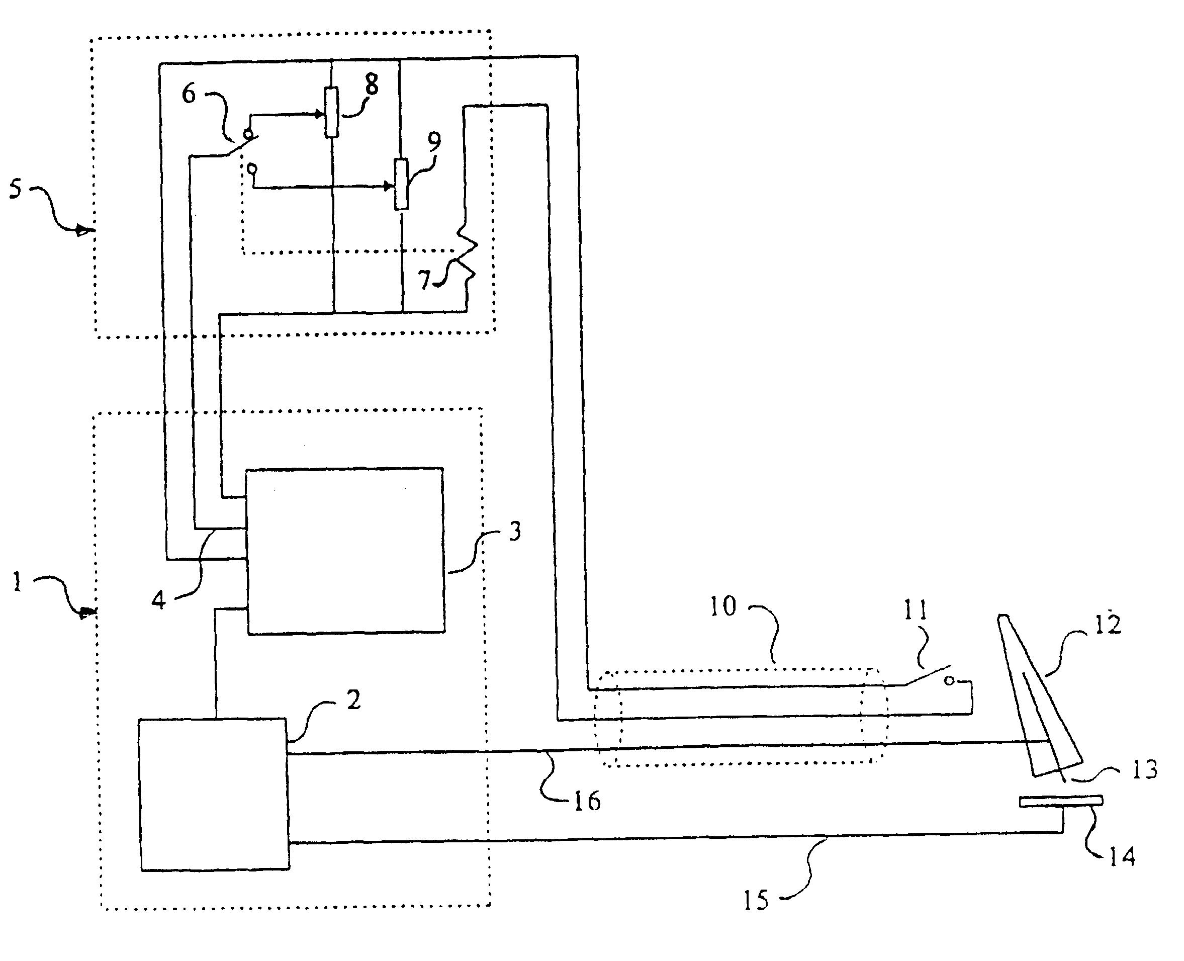
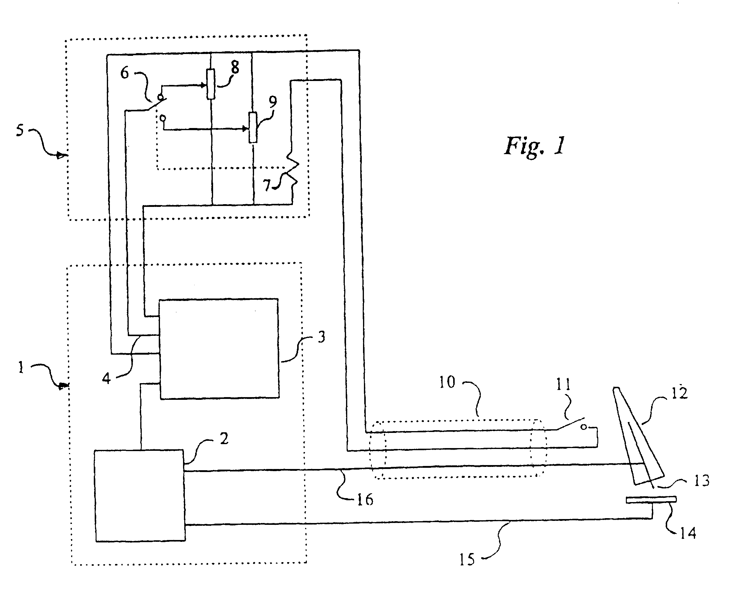
Current source 1 consisting of control part 3 and power part 2 delivers current to the welding torch 12 with its electrode 13 via the welding cable 16. The arc burns between the electrode and the workpiece 14, from which the return cable 15 leads the current back to the power part of the current source. The current set value converter 5 comprises at least two current set value adjusters 8, 9 and a selector member 6 which is controlled from the gun trigger 11 which is preferably placed on or in immediate proximity to the welding torch 12. Welding hose 10 and an input for current set value 4 are other units shown in FIG. 1.

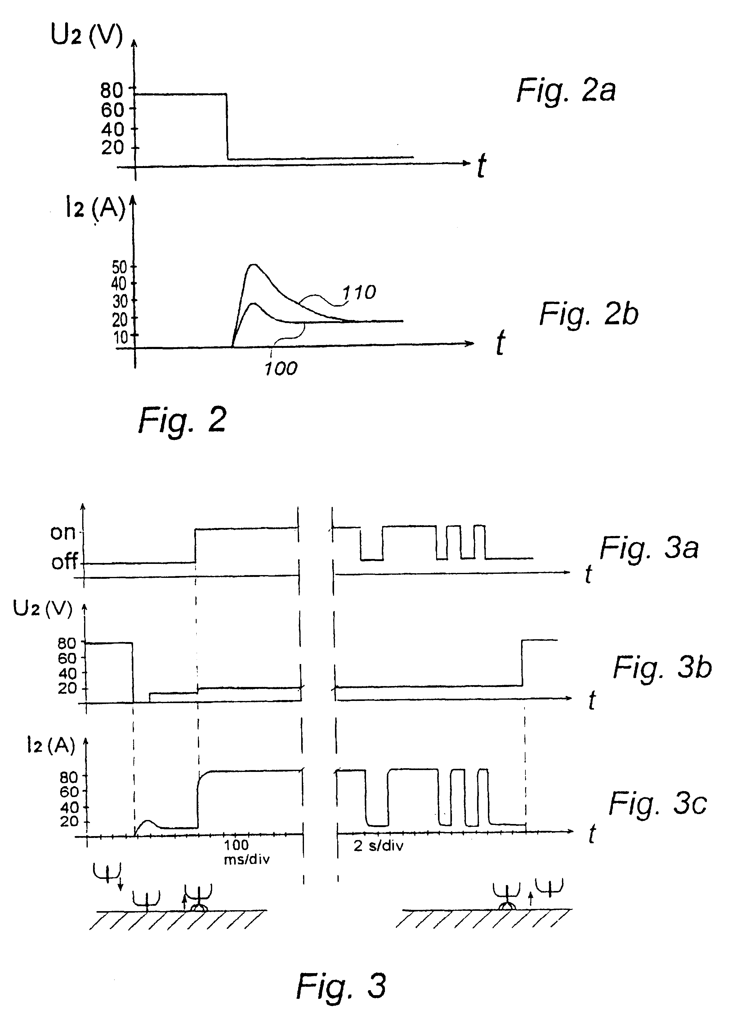
FIG. 2 shows the voltage U.sub.2 between the welding cable and the return cable 15 and the current I.sub.2 in these cables as a function of the time during a start-up procedure. The curve 110 in FIG. 2b indicates a powerful starting current surge, as often occurs in MMA mac...


PUM

PropertyMeasurementUnit
timeaaaaaaaaaa
timeaaaaaaaaaa
currentaaaaaaaaaa

Abstract

The invention relates to an arrangement for contact arc ignition in manual TIG welding and to a method for welding with this arrangement. The arc is established by lifting the welding torch (12) after contact between electrode (13) and workpiece (14) under low ignition current. When the arc length is sufficient, the welder orders a change-over to welding current via an operating device (11). The invention can also be used for controlling the supply of heat to the workpiece both during continuous bead application and during the crater filling time at the end of welding. The invention creates reliable ignitions without extensive use of control electronics, and it substantially reduces the electrode wear in manual TIG welding.

Description

The present invention relates to an arrangement for contact arc ignition in manual TIG welding.In TIG welding today, there are principally three different methods for establishing the arc.Contactless ignition by means of the protective gas being ionized by high-frequency high voltage. This method is called HP ignition and is regularly used in high-quality welding, where it is important that no inclusions of the electrode material are present in the weld deposit. The method provides good starts, but it also has disadvantages such as a high cost and often very disruptive radiation. This means that the method cannot be used in electrically sensitive environments.Contact ignition according to the LIFTARC.RTM. ignition method in which the electrode is brought into contact with the workpiece. Thereafter the welding gun trigger is pressed and the current source delivers a low current until the gun is lifted and an arc voltage can thereby be detected. The current is then raised automaticall...

Claims


Application Information

Patent Timeline
Patent Type & Authority Patents(United States)
IPC IPC(8): B23K9/06B23K9/067
CPCB23K9/0672
Inventor KARLSSON, ROLF
Owner ESAB AB
Learn More