Eureka AIR delivers breakthrough ideas for toughest innovation challenges, trusted by R&D personnel around the world.

Drive unit

a technology of drive unit and drive shaft, which is applied in the direction of mechanical roughness/irregularity measurement, instruments, etc., can solve the problems of affecting the straightness of the sliding shaft, affecting the linearity of the measuring tool secured to the sliding shaft, and affecting the stability of the sliding sha

Inactive Publication Date: 2002-07-30
MITUTOYO CORP
View PDF2 Cites 12 Cited by
  • Summary
  • Abstract
  • Description
  • Claims
  • Application Information

AI Technical Summary

Benefits of technology

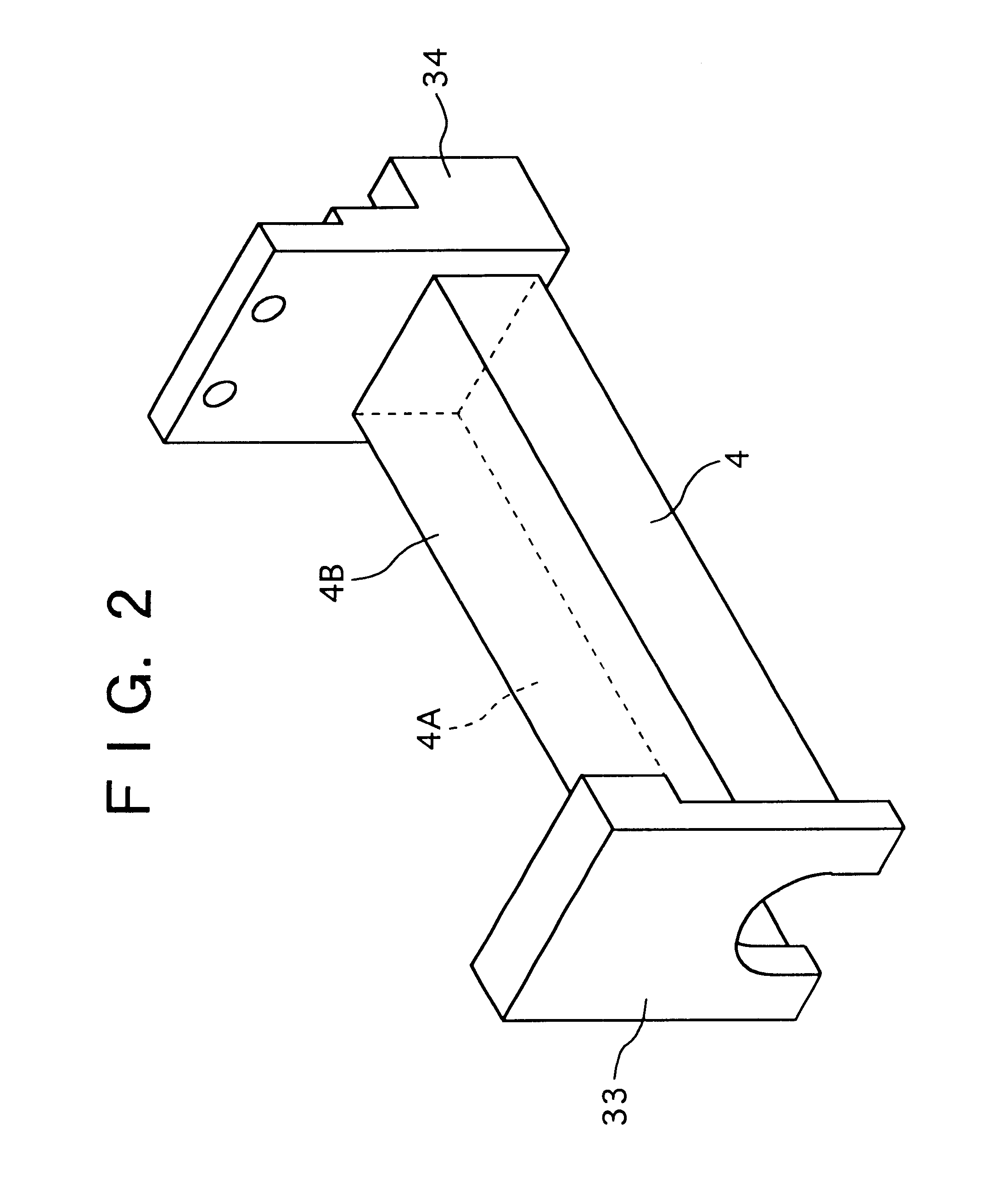
According to the present invention, the slider holding the measuring tool is moved without being rotated along a single guide rail having at least two reference surfaces parallel with the moving direction of the measuring tool, the reference surfaces retaining a predetermined angle with each other. Accordingly, since the cross section of the guide rail can be enlarged without increasing the size of the entire drive unit, the size and weight of the drive unit can be reduced while securing high rigidity as compared to a conventional arrangement having the two shafts. Therefore, the linearity of the moving direction of the slider and the measuring tool being moved along the reference surfaces of the guide rail can be achieved with high accuracy.
According to the present invention, since both ends of the guide rail are integrally fixed to frame, the size of the guide rail can be increased relative to the size of the drive unit, thus further enhancing the rigidity of the frame. Therefore, when the drive unit itself is supported by a cantilever construction, since the frame and the guide rail do not distort, the linearity of the moving direction of the measuring tool can be maintained.

Problems solved by technology

Since the sliding shaft of the drive unit is formed of a small diameter rod, flexure, for example, can be generated to the sliding shaft, thus impairing straightness of the sliding shaft.
Accordingly, the linearity of the measuring tool secured to the sliding shaft can be impaired.
However, since the drive unit of the related art 2 is arranged to move the slider holding the measuring tool along the main shaft while being engaged to the sub-shaft so that the slider does not rotate relative to the main shaft, structure thereof can be complicated on account of the need for providing the sub-shaft for preventing rotation of the slider relative to the main shaft, and the size and weight thereof can be increased.

Method used


Image

  • Drive unit
  • Drive unit
  • Drive unit

Examples


Embodiment Construction

A preferred embodiment of the present invention will be described below with reference to attached drawings.

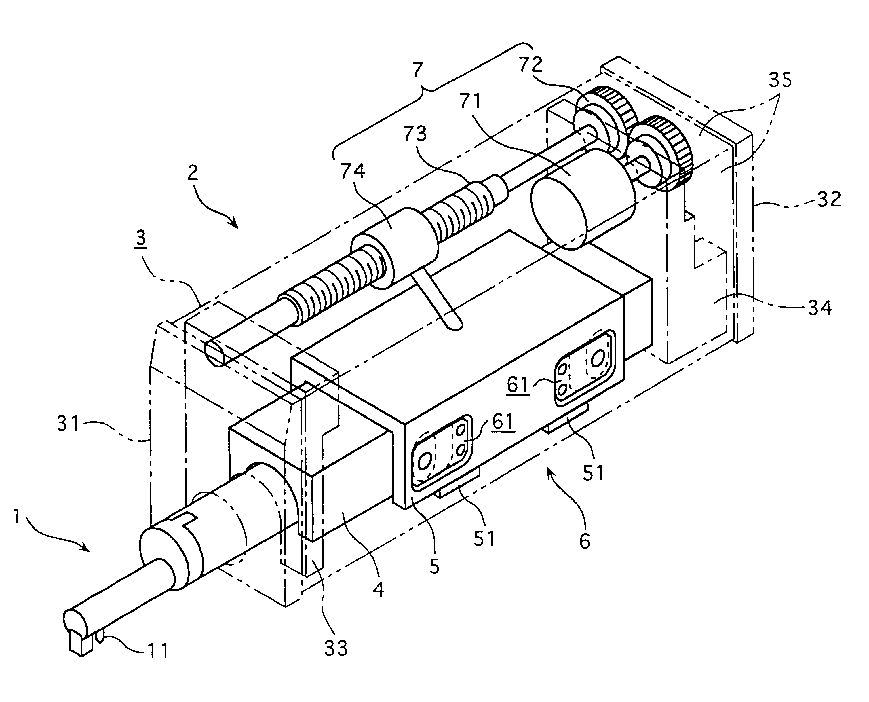
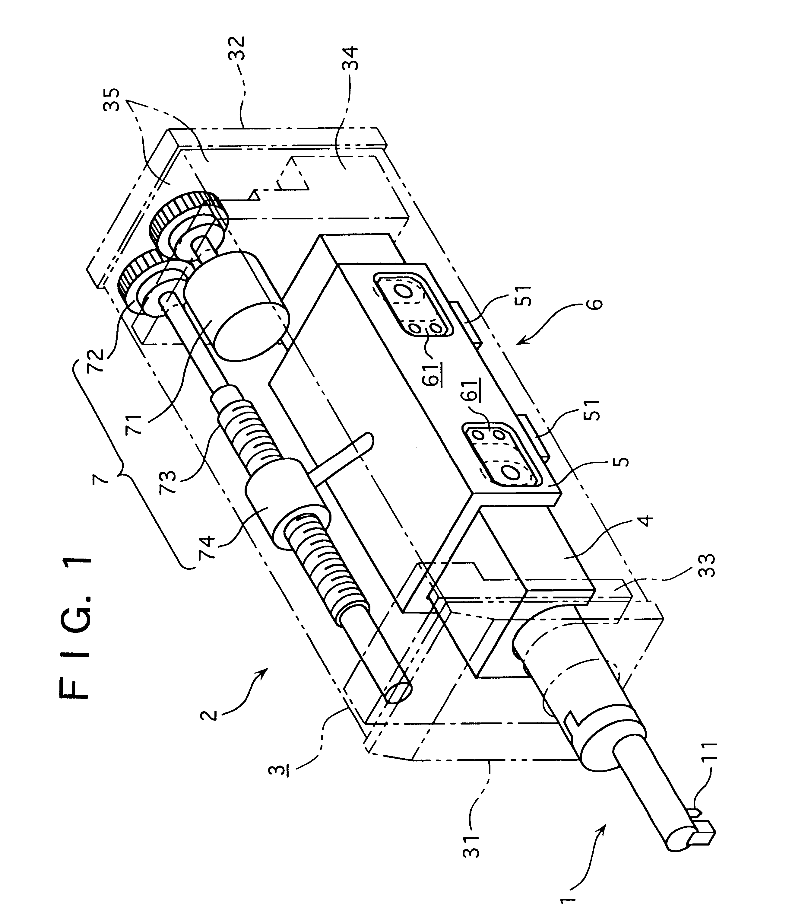
FIG. 1 shows a drive unit 2 holding a measuring tool 1 for measuring surface roughness, waviness, and form of a workpiece. The measuring tool 1 has a stylus 11 to be in contact with a surface of a workpiece, the stylus 11 detecting the surface roughness etc. based on vertical displacement thereof.

The drive unit 2 has a box-shaped frame 3, a guide rail 4 provided to the frame 3 and extending in parallel with the moving direction of the measuring tool 1, a slider 5 slidable along the guide rail 4 and holding the measuring tool 1, a pre-load means 6 for biasing the slider 5 toward the guide rail 4, and a driver 7 for moving the slider 5 along the guide rail 4.

The frame 3 has a front guide 31 disposed on a front side (leftward in the figure), a rear guide 32 disposed opposite to the front guide 31, a front frame 33, and a rear frame 34, respectively attached to opposing sides of t...


PUM


Abstract

A slider holding a measuring tool moves along an approximately reverse U-shaped guide rail provided in parallel with a moving direction of the measuring tool without being rotated. Accordingly, a cross section of the guide rail can be enlarged without increasing the size of the entirety of a drive unit. As a result, high rigidity can be obtained while reducing the size and weight of the drive unit as compared to a conventional arrangement having two shafts. Further, linearity of the slider and the measuring tool moving along a reference surface of the guide rail can be attained with high accuracy. Further, since a pre-load means for biasing the slider toward a guide rail is provided, a position or orientation of the slider and the measuring tool can be stabilized, thus securely repeating movement of the measuring tool.

Description

1. Field of the InventionThe present invention relates to a drive unit. More specifically, it relates to a drive unit capable of moving a measuring tool for measuring surface texture of a workpiece such as surface roughness, waviness, and form along a surface of the workpiece.2. Description of Related ArtAn example of a drive unit capable of moving a measuring tool for measuring surface roughness, waviness, form etc. of a workpiece along the surface of the workpiece is known in U.S. Pat. No. 4765181 (related art 1).The drive unit has a box-shaped frame, a sliding shaft provided in the frame in parallel with a moving direction of the measuring tool and holding the measuring tool, and a driver for moving the sliding shaft along an axial direction thereof. Both ends of the sliding shaft are supported by roller bearings in a sliding manner in the axial direction.Since the sliding shaft of the drive unit is formed of a small diameter rod, flexure, for example, can be generated to the sli...

Claims


Application Information

Patent Timeline
Patent Type & Authority Patents(United States)
IPC IPC(8): B23Q1/58B23Q17/20B23Q1/25G01B5/00G01B7/34G01B7/28G12B5/00F16H25/20G01B21/30
CPCG01B7/34G01B7/28G12B5/00G01B5/0002
Inventor FUJII, NOBUYOSHIUEDA, SATOSHIDOI, FUTOSHI
Owner MITUTOYO CORP
Why Eureka
Eureka Blog
Learn More