Heat-pump water heater
a water heater and heat pump technology, applied in heat pumps, lighting and heating apparatus, heating types, etc., can solve the problems of increased compressor load, affecting normal operation of heat pump cycle, and difficulty in obtaining the necessary heating capacity of the water heater
- Summary
- Abstract
- Description
- Claims
- Application Information
AI Technical Summary
Benefits of technology
Problems solved by technology
Method used
Image

Examples
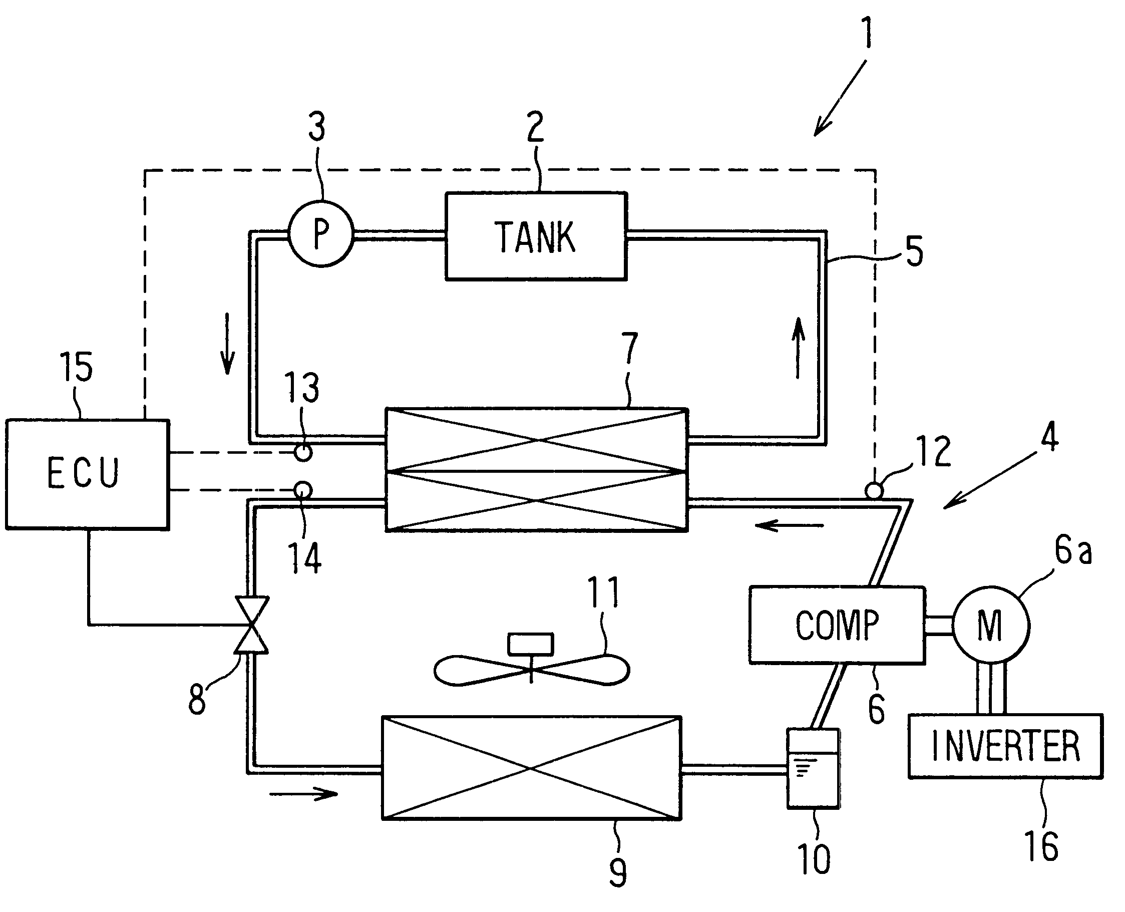
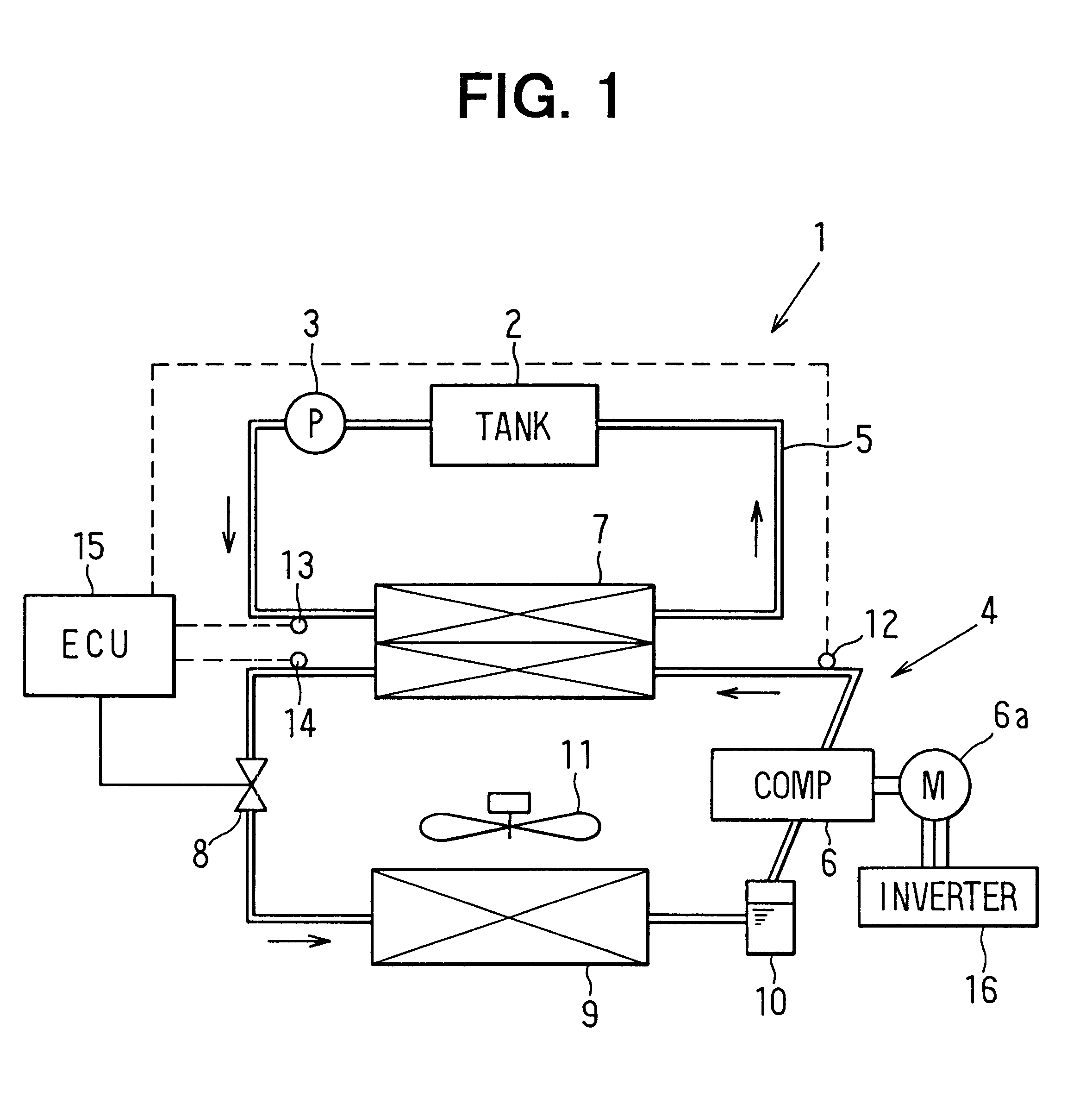
first embodiment
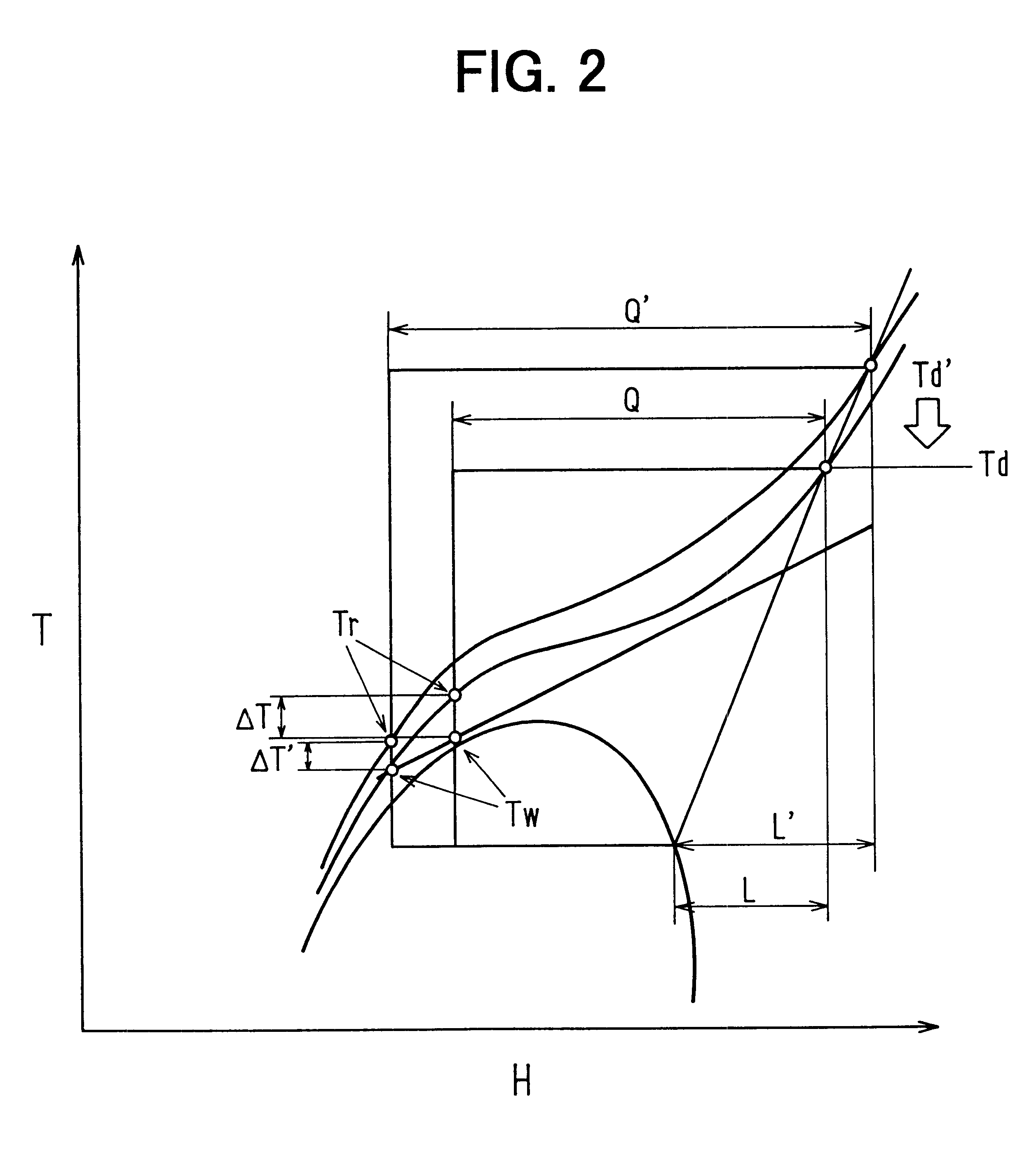
Next, the control process of the ECU 15 will be now described with reference to FIG. 3. First, at step S10, the high-pressure side refrigerant pressure of the heat pump cycle 4 is controlled by controlling the valve opening degree of the expansion valve 8, so that a set target temperature difference .DELTA.T (e.g., 10.degree. C.) is obtained. Next, at step S20, the refrigerant temperature Td discharged from the compressor 6 is detected by the first refrigerant temperature sensor 12.
At step S30, it is determined whether or not the refrigerant temperature Td discharged from the compressor 6 is equal to or higher than a predetermined value Tdp. In the first embodiment, the predetermined value Tdp is set based on a permissible upper limit temperature of the compressor 6. When it is determined that the refrigerant temperature Td discharged from the compressor 6 is equal to or higher than the predetermined value Tdp at step S30, the target temperature difference .DELTA.T is increased at ...
second embodiment
FIG. 4 is a flow diagram showing a control process of the ECU 15 according to the First, at step S110, the valve opening degree of the expansion valve 8 is controlled so that a set target temperature difference .DELTA.T can be obtained. Next, an evaporation temperature Ts of refrigerant is detected at step S120, and it is determined whether or not the evaporation temperature Ts is equal to or lower than a predetermined temperature Ts1 (i.e., protection control start temperature) at step S130. When the evaporation temperature Ts of refrigerant is equal to or lower than the predetermined temperature Ts1 at step S130, the target temperature difference .DELTA.T is determined based on the evaporation temperature Ts of refrigerant in accordance with the graph of FIG. 5. In FIG. 5, Tp indicates a protection control start point. On the other hand, when the evaporation temperature Ts of refrigerant is higher than the predetermined temperature Ts1 at step S130, the control routine moves to s...
third embodiment
FIG. 6 is a flow diagram showing a control process of the ECU 15 according to the First, at Step S210, the high-pressure side refrigerant pressure of the heat pump cycle 4 is controlled by controlling the valve opening degree of the expansion valve 8, so that a set target temperature difference .DELTA.T can be obtained. Next, at step S220, it is determined whether or not a current restriction due to the inverter circuit 16 is performed in the compressor 6. When the current restriction is performed at step S220, the target temperature difference .DELTA.T is changed to become larger (e.g., 15.degree. C.) at step S230, and thereafter, the control routine moves to step S210.
On the other hand, when the current restriction is not performed at step S220, it is determined whether or not a water heating capacity reaches a target water heating capacity at step S240. For example, the water heating capacity can be determined based on a heat quantity of hot water that is heated by refrigerant i...
PUM
 Abstract
Description
Claims
Application Information
 - R&D
- Intellectual Property
- Life Sciences
- Materials
- Tech Scout
- Unparalleled Data Quality
- Higher Quality Content
- 60% Fewer Hallucinations
Browse by: Latest US Patents, China's latest patents, Technical Efficacy Thesaurus, Application Domain, Technology Topic, Popular Technical Reports.
© 2025 PatSnap. All rights reserved.Legal|Privacy policy|Modern Slavery Act Transparency Statement|Sitemap|About US| Contact US: help@patsnap.com