Ultrasonic method of fabricating a thermosetting matrix fiber-reinforced composite structure and the product thereof

a thermosetting matrix fiber and composite structure technology, applied in the direction of lamination apparatus, layered products, chemistry apparatus and processes, etc., can solve the problems of degrading the mechanical properties of the cured part, the viscosity of the resin cannot be lowered, and the process can take a matter of hours, so as to reduce or eliminate the repeated debulking operations, enhance the interlaminar properties of ply to ply, and reduce the effect of repeated debulking operations

Inactive Publication Date: 2002-08-13
NORTHROP GRUMMAN INNOVATION SYST INC
View PDF7 Cites 86 Cited by
  • Summary
  • Abstract
  • Description
  • Claims
  • Application Information

AI Technical Summary

Benefits of technology

It is a further object of this invention to provide such a method which is controllable, instantly modulatable, and which does not require a large thermal differential between the device and the material.
This invention features a method of fabricating a thermosetting matrix, fiber reinforced composite structure. The method comprises assembling a stack of fiber reinforced thermosetting material plies, engaging an ultrasonic horn with a top surface of the upper most ply; and orienting the horn at an acute angle with respect to the top surface and energizing the horn to induce a shear wave in the plies to heat the plies. Typically, the horn is moved along the upper most ply to consolidate the plies. The energy level applied by the horn is sufficient to reduce the viscosity of the thermoset resin to the point where the plies can be debulked but not high enough to fully cross-link the resin so that another ply can still be fully cross-lined to the uppermost ply. Pressure is applied to the plies via the horn and / or a separate roller or shoe to debulk the plies.

Problems solved by technology

This process can take a matter of hours.
Once this chemical cross linking occurs, the viscosity of the resin cannot be lowered.
Thick parts cured without any intermediate debulks often develop fiber wrinkling, which degrades the mechanical properties of the cured part.
One obstacle to consistently achieving higher levels of consolidation with these processes is the difficulty inherent in controlling temperature.
Because of the heat capacity present in a hot gas system, the temperature of the gas jet, and hence the heat input to the tow, cannot be easily modulated to allow for starts, stops or changes in advance rate of the robotic head.
Current thick parts such as the V-22 spindle and the F-22 pivot shaft require numerous intermediate debulks, which adds substantial cost.
Obeda, however, teaches nothing about composite materials.
These previous attempts to weld even thermoplastic composites during the lamination process, using conventional ultrasonic perpendicularly disposed horn welding techniques, have yielded disappointing results because, it is speculated, the presence of the fibers alters the energy transfer in the material.
Moreover, these conventional ultrasonic welding techniques set up a compression wavefront in the material which does not transmit well through the material.
The result, however, was not satisfactory: "C-Scan results have shown that attempts to produce consolidated or near-consolidated laminates have not been successful thus far .
Therefore, although ultrasonic horns have been used to weld plastic sheets together and, to some extent, have been successfully used to weld thermoplastics containing up to about 35% filler (such as glass or talc), the state of the art reveals no successful methodology of fabricating thermosetting or thermoplastic resin fiber matrix composite structures wherein an ultrasonic horn is used to consolidate and debulk the individual fiber-resin plies.

Method used


Image

  • Ultrasonic method of fabricating a thermosetting matrix fiber-reinforced composite structure and the product thereof
  • Ultrasonic method of fabricating a thermosetting matrix fiber-reinforced composite structure and the product thereof
  • Ultrasonic method of fabricating a thermosetting matrix fiber-reinforced composite structure and the product thereof

Examples


Embodiment Construction

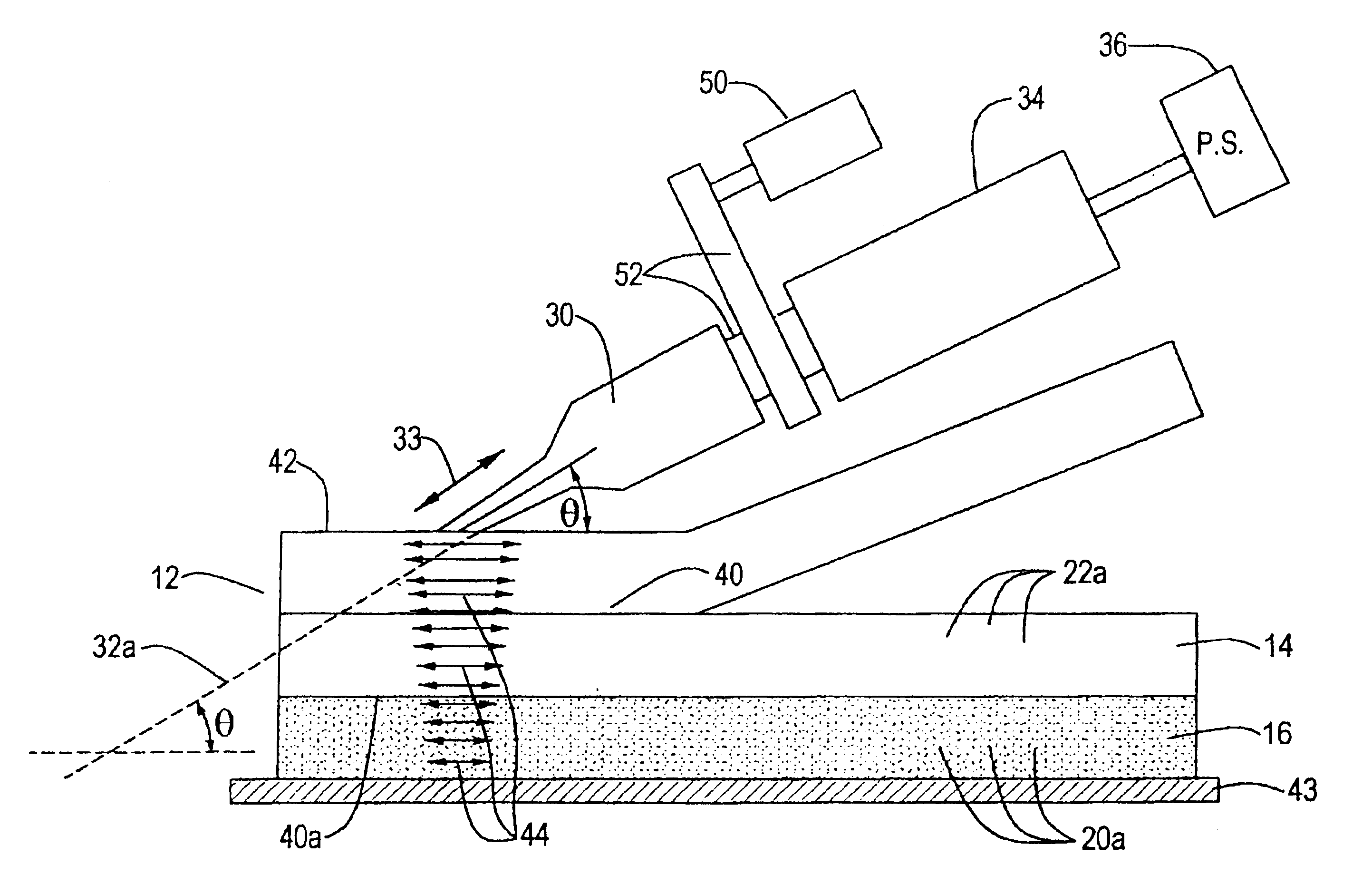
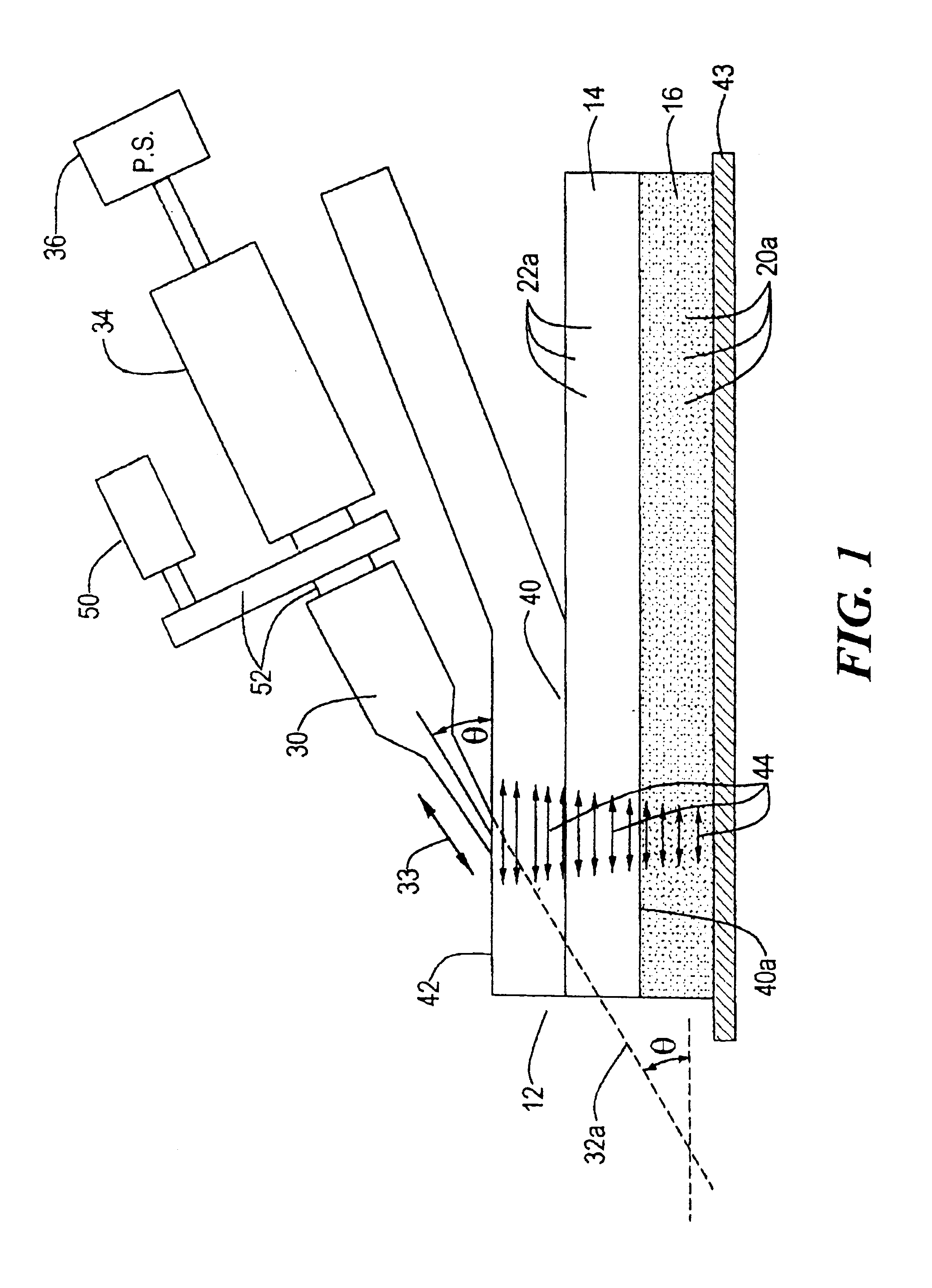
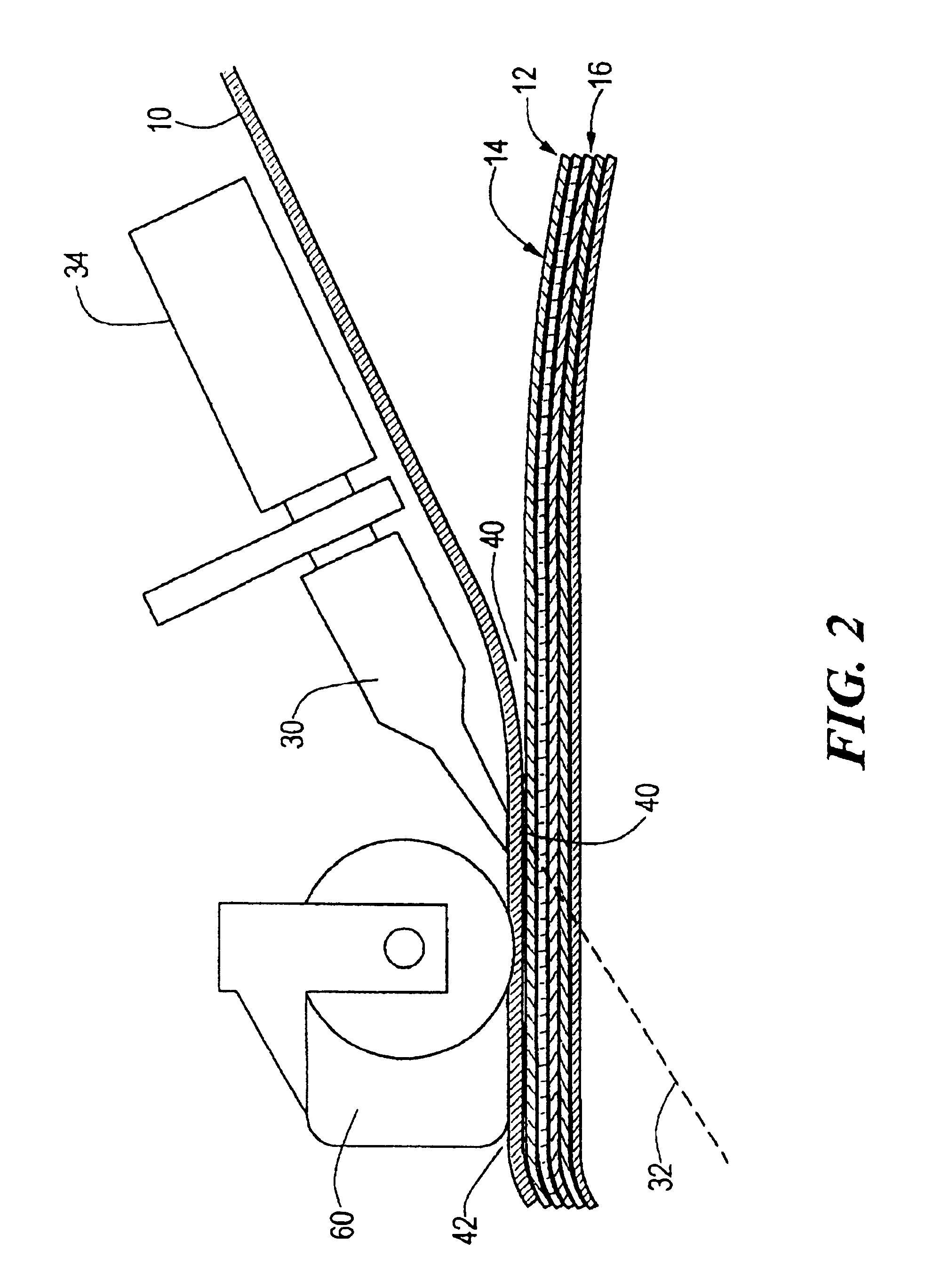
There is shown in FIG. 1 one thermosetting resin matrix, fiber-reinforced composite ply 10 (layer, tow, ribbon, or tape) in the process of being applied to other thermosetting-resin matrix, fiber-reinforced composite plies 14 and 16. Ultrasonic energy is applied to a modified horn 30, which is vibrated in the direction shown by arrow 33 along its longitudinal axis 32 by ultrasonic transducer 34 driven by power supply 36.

In the prior art, the ultrasonic horn 30 was placed perpendicular to plies of thermoplastic materials and the resulting ultrasonic stress waves were generally understood to be compression waves which moved perpendicularly through the plies.

As explained in the Background of the Invention above, this prior art technique, wherein the ultrasonic horn is placed perpendicular to the plies, has met with indifferent success. It is believed this is in part because the fibers in ply 10 affect and dissipate the energy before it can be converted to heat at the interface 40 betwe...


PUM

PropertyMeasurementUnit
widthaaaaaaaaaa
frequenciesaaaaaaaaaa
frequencyaaaaaaaaaa

Abstract

A method of fabricating a thermosetting matrix, fiber reinforced composite structure wherein a stack of fiber reinforced thermosetting material plies are assembled; an ultrasonic horn is engaged with a top surface of the upper most ply, oriented at an acute angle with respect to the top surface, and energized to induce a shear wave in the plies to heat the plies. The horn is moved along the upper most ply to consolidate the plies and the energy level applied to the horn is sufficient to reduce the viscosity of the thermoset resin to the point where the plies can be debulked but not high enough to fully cross-link the resin so that another ply can still be fully cross-linked to the uppermost ply. Pressure is applied to the plies as the horn moves to debulk the plies.

Description

This invention relates to an improved method of ultrasonically consolidating layers or plies of fiber-reinforced thermosetting resin matrix composite materials and more particularly to such a method which applies the ultrasonic energy generally parallel to the surface of the layer to produce substantial shear in the plies to effect heating of the resin matrix. The invention also relates to the product made by that method.BACKGROUND OF INVENTIONComposite materials are becoming more and more attractive for a wide variety of uses, from aircraft and automobiles to sporting goods and toys, because of their high stiffness and strength-to-weight ratio. One type of composite material includes a combination of fibers or fibrous tows in a matrix of thermosetting resin. Typically, such a composite structure is made of a number of layers of plies of "prepreg" tape. As used herein, a composite material means a structure composed of a plurality of plies of fiber-reinforced fabric or tape in a the...

Claims


Application Information

Patent Timeline
Patent Type & Authority Patents(United States)
IPC IPC(8): B29C65/08B29C70/04B29C70/54B29C70/38B29C53/56B29C53/00
CPCB29C65/08B29C65/081B29C66/80B29C66/836B29C70/382B29C70/386B29C70/543B29C66/73121B29C66/9513B29C66/8362B29C53/56B29C66/9516B29C66/7212B29C66/72143B29C66/72141B29C66/721B29C66/73941B29C66/432B29C66/73754B29C66/472B29C66/4722B29C66/8244B29C66/8161B29C66/8242B29C66/1122B29K2307/04B29K2309/08B29K2277/10
Inventor LEEMON, VICTORBULLOCK, DANIEL E.ROYLANCE, MARGARET E.WOODS, JACK A.BOYCE, JOSEPH S.PLAYER, JOHN C.
Owner NORTHROP GRUMMAN INNOVATION SYST INC
Why Eureka
Try Eureka