
Biopsy system

Inactive Publication Date: 2002-08-20
UNITED STATES SURGICAL CORP
View PDF181 Cites 308 Cited by
  • Summary
  • Abstract
  • Description
  • Claims
  • Application Information

AI Technical Summary

Benefits of technology

In another embodiment, the firing module has a module latch assembly for releasably engaging the firing module with the carriage housing. The module latch assembly includes a release button to release the firing module from the carriage housing. A firing release assembly is included to prevent firing of the hammer when the firing module is disengaged from the housing. A ram is included which is mounted to a rocker arm facilitating motion of the ram. The rocker arm can be actuated by springs. A trigger button engages a latch assembly that releases the rocker arm. The rocker arm causes the ram to drive the insertion unit into a lesion of a patient.
In a further alternative embodiment, a biopsy system, in accordance with the present disclosure is provided. The biopsy system includes a housing and a biopsy instrument operatively associated with the housing. The biopsy instrument is configured and dimensioned to remove a tissue sample from a patient. The biopsy instrument may include a tissue receiving portion. A firing module similar to that previously noted is detachably engageable with the housing and operatively associated with the biopsy instrument to facilitate selective rapid advancement of at least a portion of the biopsy instrument toward a targeted location with the patient. The biopsy system is adaptable to fit on an upright diagnostic biopsy table. Further, the biopsy instrument can be removable from the biopsy system.
In another embodiment, the biopsy instrument includes a drive apparatus having a housing and a carriage assembly slidably disposed within the housing. The carriage assembly is adapted to receive and removably retain a biopsy instrument. A firing module is detachably engageable with the housing and operatively associated with the carriage assembly to facilitate selective rapid linear advancement of the carriage assembly.

Problems solved by technology

The type of biopsy utilized depends in large part on the circumstances present with respect to the patient and no single procedure is ideal for all cases.
However, definitive tissue characterization still requires obtaining adequate tissue samples to characterize the histology of the organ or lesion.
It is still difficult to determine if pre-palpable breast abnormalities are malignant, as some benign lesions have mammographic features which mimic malignant lesions and some malignant lesions have mammographic features which mimic benign lesions.
Thus, mammography has its limitations.
Biopsy devices used in connection with the above-mentioned guidance systems, particularly those used for diagnostic procedures, suffered from various drawbacks.
Use of current devices can be limited due to their length.
Current designs may be too long or contain configurations for particular mammography tables.
Therefore, the above-mentioned devices may not be usable with more than one guidance system without modification or may not be adaptable at all.
Another disadvantage of current devices is the inability to recall at what position a previous sample was taken.
Another drawback suffered by current devices is severing tissue with a knife that is hand driven.
This results in inconsistent sample size due to resilient tissue that may be encountered.
Further, the firing of a biopsy gun and manipulation of a biopsy device into tissue may cause undesired collateral damage to untargeted tissue and surrounding bodily structures which may result in poor tissue sampling.

Method used


Image

  • Biopsy system
  • Biopsy system
  • Biopsy system

Examples


Embodiment Construction

The present disclosure is directed to a biopsy system and method for the biopsy of tissue specimens and, more particularly, to a single insertion multiple sample percutaneous biopsy system and method.

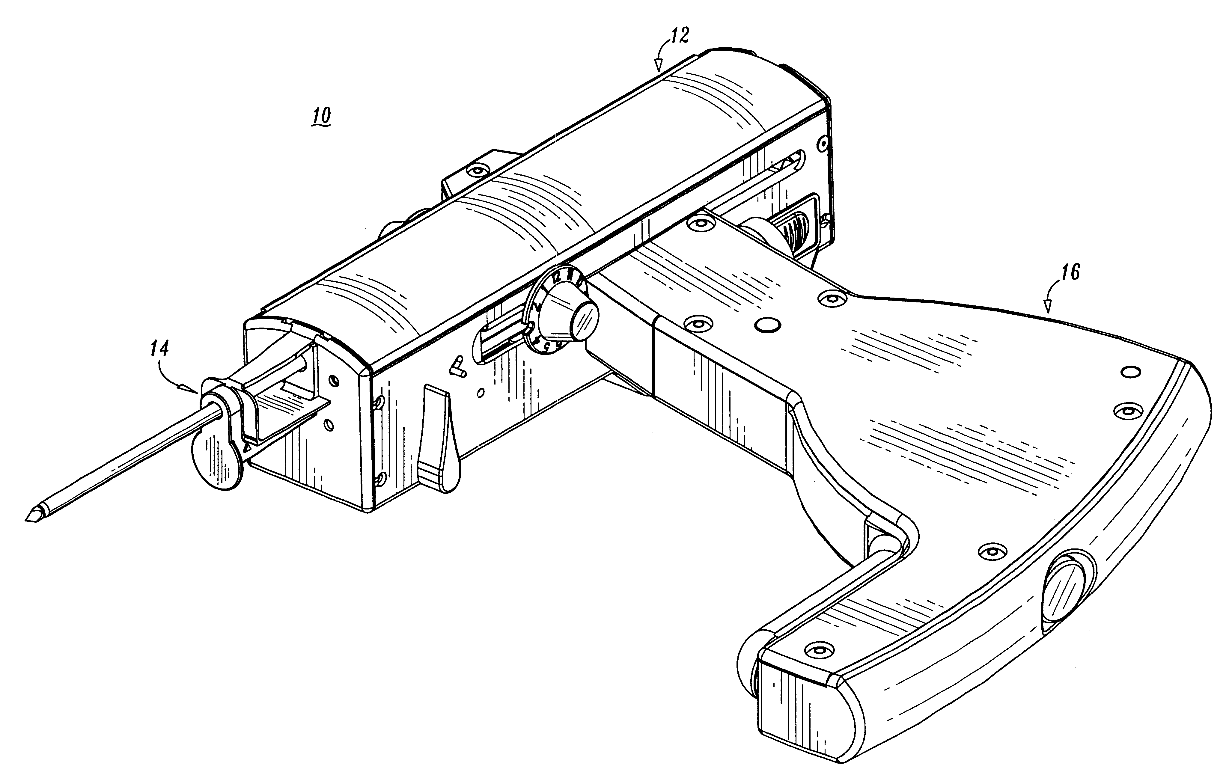
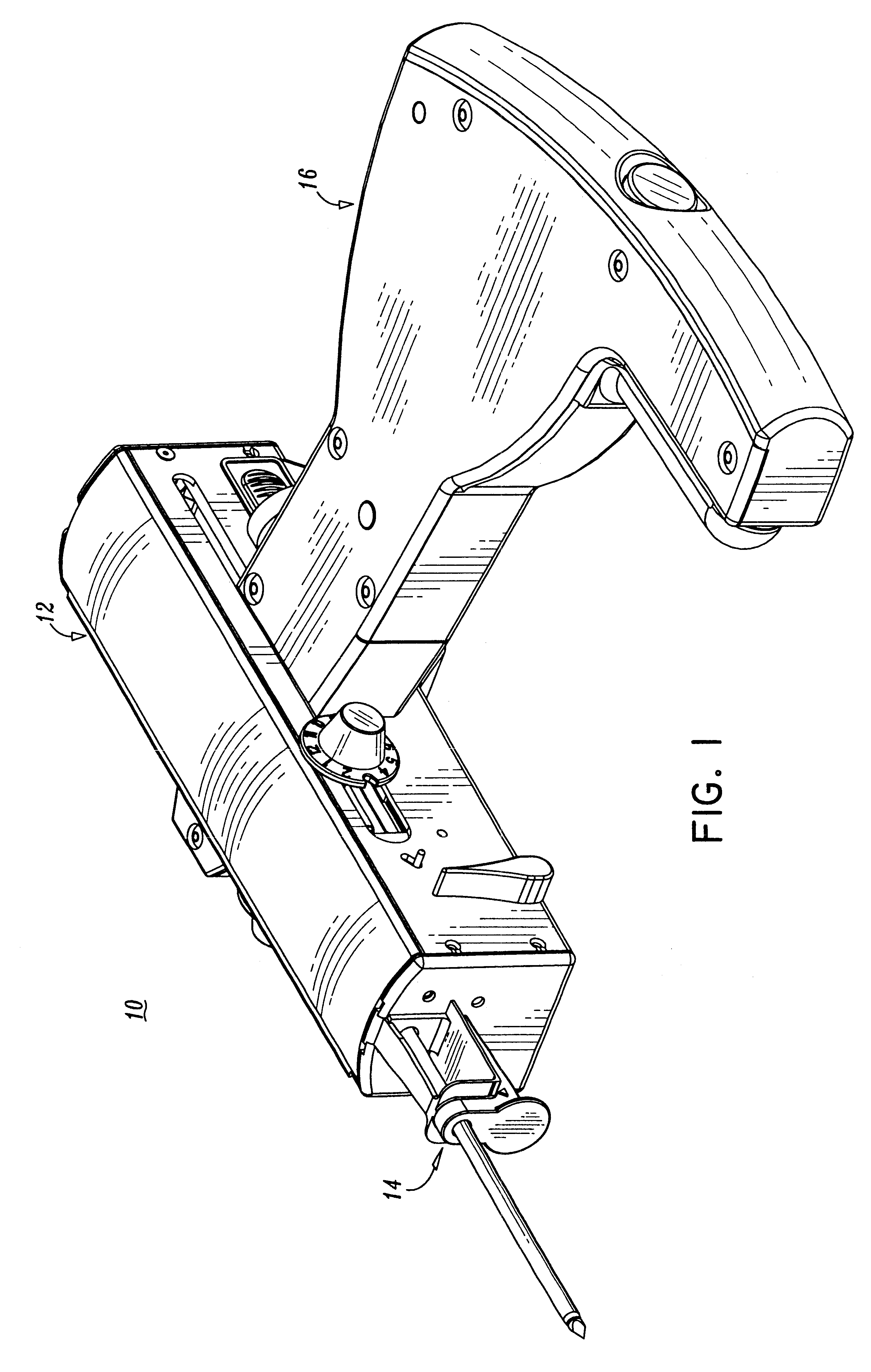
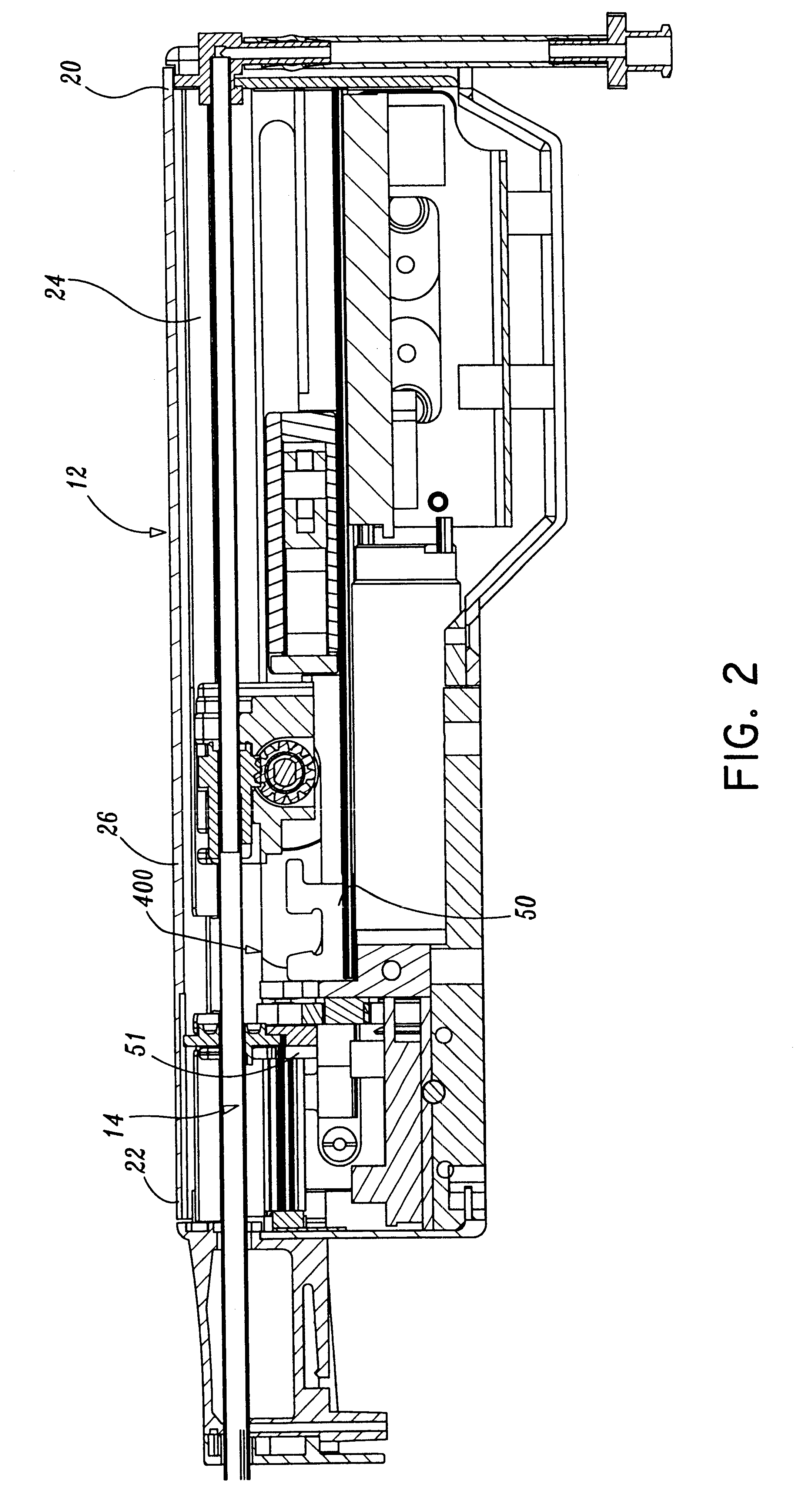
In general, as shown in FIG. 1, the biopsy system hereinafter referred to as biopsy apparatus 10 includes a carriage housing 12, a biopsy instrument, such as, for example, insertion unit 14, and a firing module 16. These elements of the apparatus cooperate to facilitate retrieval of multiple tissue specimens wherein insertion unit 14 includes a vacuum tube 76 having a tip portion, such as, for example, a penetrating tip 78 and a lateral opening, such as, for example, a tissue basket 80 that is introduced into a target mass in a patient's breast. Suction is applied which is communicated to an area adjacent tissue basket 80 to a vacuum plate, such as, for example, a tissue support plate 82 to draw at least a portion of the target tissue mass into tissue basket 80. A knife tube 64 is advan...


PUM


Abstract

A biopsy system is provided including a housing and a biopsy instrument operatively associated with the housing and configured and dimensioned to remove a tissue sample from a patient. A firing module is included that is detachably engageable with the housing and operatively associated with the biopsy instrument to facilitate selective rapid advancement of at least a portion of the biopsy instrument toward a targeted location with the patient. The biopsy instrument includes a tissue receiving portion. The system may include an indexing assembly disposed within the housing and configured to cooperate with the biopsy instrument to selectively orient the tissue receiving portion. The indexing assembly may include a manual gearing assembly configured for selective orientation of the tissue receiving portion. The system may include a linear advancement control assembly disposed within the housing and configured to effect linear actuation of a tubular knife member. An optical sensor may be disposed adjacent a portion of the tubular knife member and oriented to detect the orientation of a lateral opening formed through the tubular knife member. A carriage may be slidably disposed within the housing and configured to releasably retain at least a portion of the biopsy instrument. A method of performing a surgical biopsy is disclosed.

Description

1. Technical FieldThis disclosure relates to a system and method for the biopsy of tissue specimens and, more particularly, to a single insertion, multiple sample percutaneous biopsy system and method.2. Background of Related ArtIt is often necessary to sample tissue in order to diagnose and treat patients suspected of having cancerous tumors, pre-malignant conditions and other diseases or disorders. Typically, in the case of suspected cancerous tissue, when the physician establishes by means of procedures such as palpation, x-ray or ultrasound imaging that suspicious conditions exist, a biopsy is performed to determine whether the cells are cancerous. Biopsy may be done by an open or percutaneous technique. Open biopsy removes the entire mass (excisional biopsy) or a part of the mass (incisional biopsy). Percutaneous biopsy on the other hand is usually done with a needle-like instrument and may be either a fine needle aspiration (FNA) or a core biopsy. In FNA biopsy, individual cel...

Claims


Application Information

Patent Timeline
IPC IPC(8): A61B10/00A61B10/02A61B17/3211A61B19/00
CPCA61B10/0275A61B10/0283A61B2010/0225
Inventor VIOLA, FRANKRETHY, CSABA L.IVANKO, DAVIDMARTINELLI, SCOTTJANKOWSKI, BRUCELEHN, RANDOLPHDALE, JAMESSTICKNEY, ARTHUREHRENFELS, KARL
Owner UNITED STATES SURGICAL CORP
Learn More