Implementation method for adaptive equalizer in CMOS

a technology of equalizer and implementation method, which is applied in the direction of transmission, electrical apparatus, pulse shaping, etc., can solve the problems of high jitter in the output signal of the equalizer, feedback error signal, and attenuation of digital pulses transmitted through telephone lines

Inactive Publication Date: 2002-08-20
PMC-SIERRA
View PDF4 Cites 16 Cited by
  • Summary
  • Abstract
  • Description
  • Claims
  • Application Information

AI Technical Summary

Problems solved by technology

It is well known that digital pulses transmitted through telephone lines become attenuated and very distorted.
The comparing circuit generates a feedback error signal which is proportional to the loss incurred in the telephone line.
The main drawbacks of the method are that the single pole-zero pair causes high jitter in the output signal from the equalizer.
The method is not suitable for monolithic integrated circuit implementation.
The main disadvantages of this method is its limited tuning range, and that the components of the model are hard wired.
The disadvantages of this method are its low flexibility, its limited tuning range, and that the components of the model are hard wired.
The main disadvantages of the method are that it is inherently low speed, and that there is need for a special clock signal for sampling, which clock speed is much higher than the data rate.
The main disadvantages of this method are that it has low flexibility, and there is a need for several operational regions due to the components having limited tuning range.

Method used


Image

  • Implementation method for adaptive equalizer in CMOS
  • Implementation method for adaptive equalizer in CMOS

Examples


Embodiment Construction

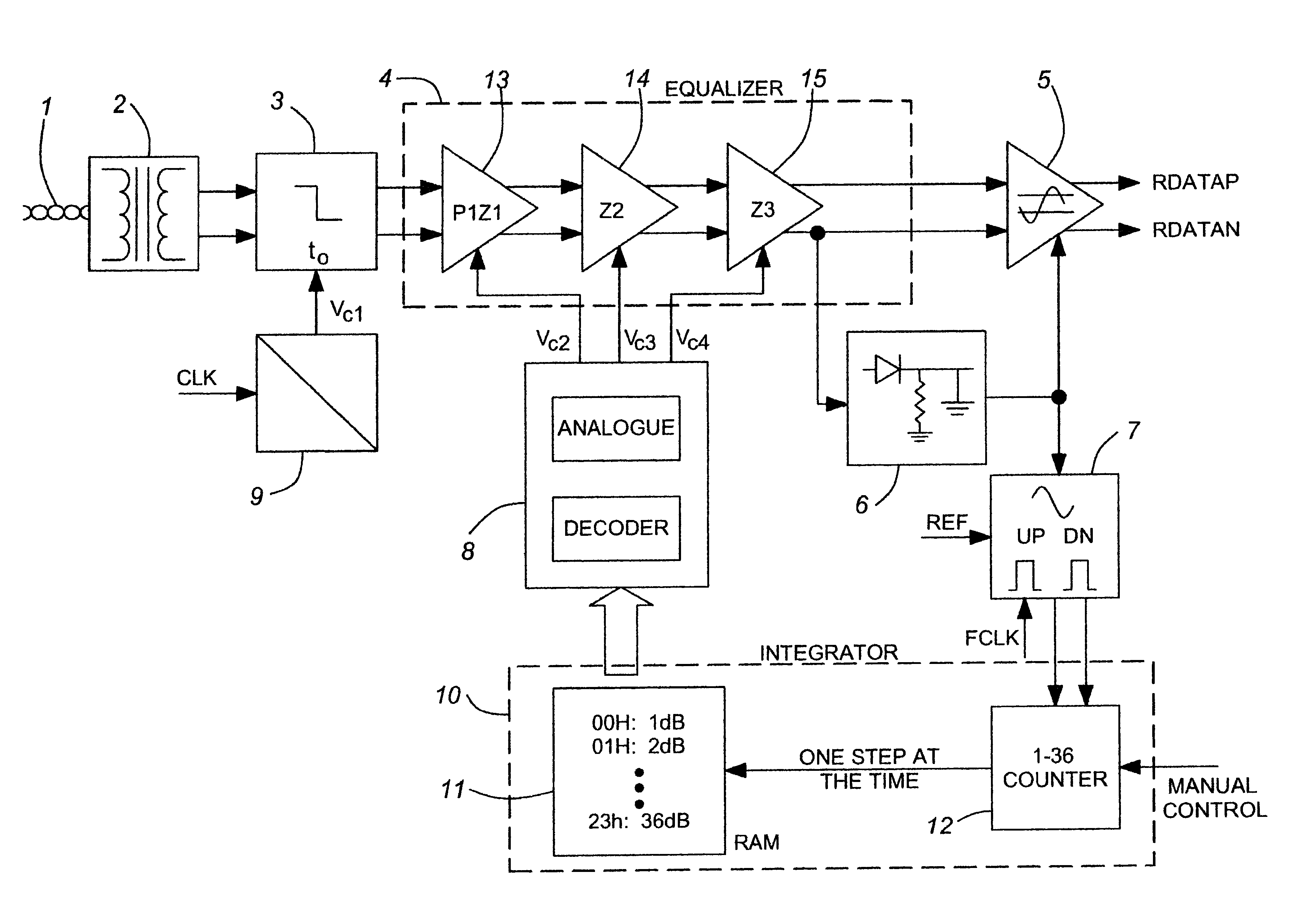
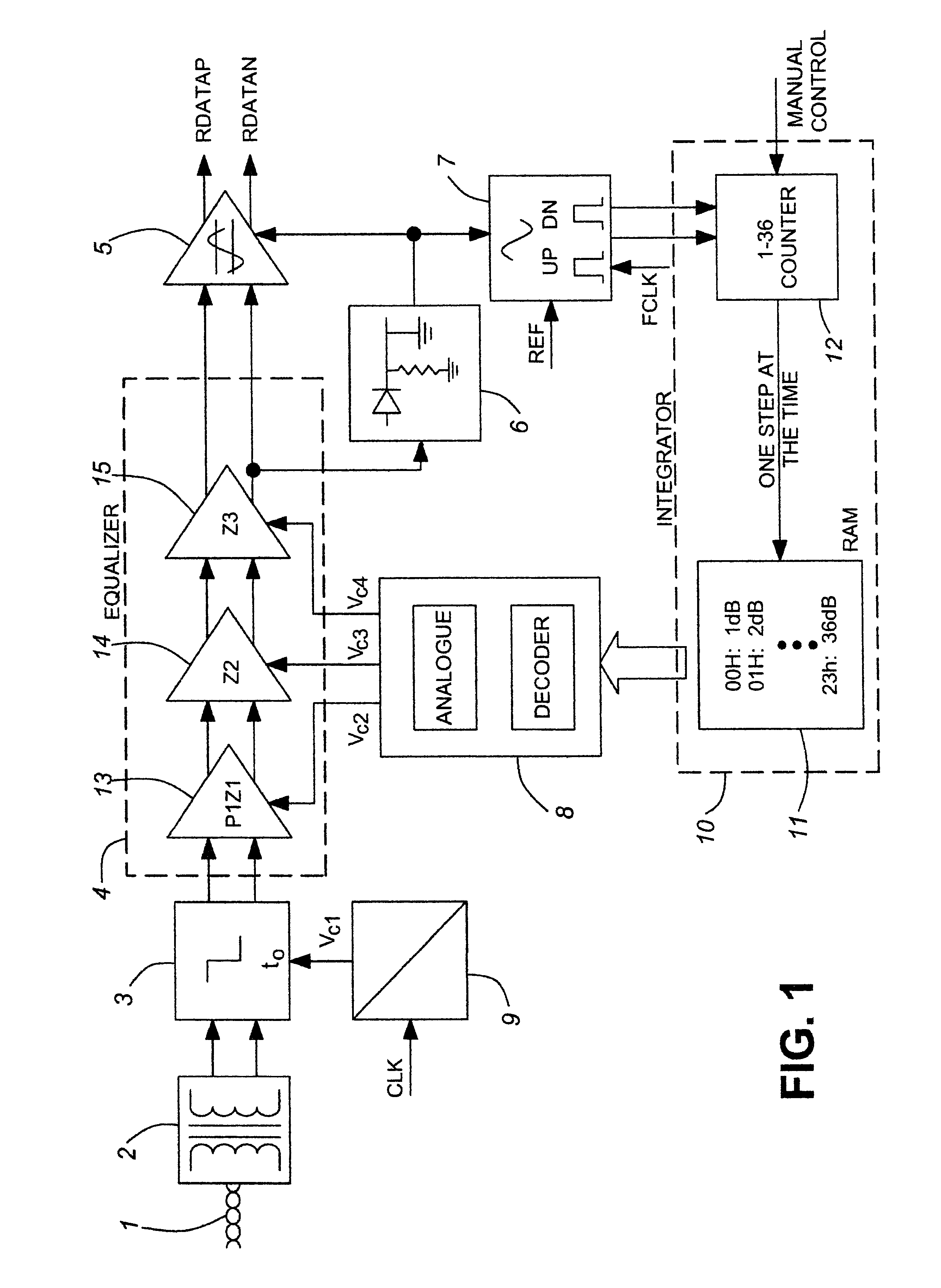
A transmission cable 1 is coupled via a transformer 2 and a band limiting filter 3 to the input of an equalizer 4. The output of the equalizer is coupled to the input of a digital pulse generator (e.g. a slicer) 5.

An output of the equalizer is coupled to the input of a peak detector 6, the output of which is coupled to the input of a feedback control circuit 7 and to a control input of the slicer 5. The output of the feedback control circuit 7 is coupled to the input of a counter 12, the output of which is coupled to address decode inputs of a memory 11, shown as a random access memory RAM.

The output of the memory 11 is coupled to the input of an equalizer control circuit 8 which is comprised of a decoder for the read output data from memory 11 and an analog control signal generation circuit which is controlled by the decoded output data from memory 11.

The analog output signals from equalizer control circuit 8 is applied to control inputs of equalizer 4 to control its transfer funct...


PUM


Abstract

An apparatus and method for restoring digital pulses within a data transmission system which have degraded due to the attenuation and distortion inherent in a data transmission medium. The apparatus comprises an adaptive equalizer which receives signals from the data transmission medium, while the method by which the digital pulses are restored comprises: storing plural equalizer transfer function control values in a memory, passing the signal through an equalizer having a controllable transfer function, comparing a characteristic of the output signal of the equalizer with a reference signal and producing a difference signal, using the difference signal to select a set of stored transfer function control values from the memory, controlling the equalizer from the selected transfer function control values so as to minimize their difference from the reference signal. This apparatus and method are suitable for high-speed applications such as T1 and E1, requiring minimal configuration by the user.

Description

This invention relates to the field of digital transmission, and in particular to an adaptive equalizer.BACKGROUND TO THE INVENTIONIt is well known that digital pulses transmitted through telephone lines become attenuated and very distorted. Both the attenuation and the distortion are nonlinear functions of both length of the telephone line and the transmission frequency. Equalizers are used to restore the pulses to their original amplitude and shape, but introduce some jitter.General approaches to solve the attenuation and distortion problems utilize a peak detector of one type or another to measure the amplitude of the incoming signal and compare it with some reference. Reconstitution can be effected since the amplitude and shape of the original signal at the transmitter is known. The comparing circuit generates a feedback error signal which is proportional to the loss incurred in the telephone line. The error signal is used to adjust the transfer function of the equalizer until t...

Claims


Application Information

Patent Timeline
Patent Type & Authority Patents(United States)
IPC IPC(8): H03K5/08
CPCH03K5/082H04L25/03878
Inventor BOYD, GRAEME B.SOBOT, ROBERTCULLEY, DAVID HEATH
Owner PMC-SIERRA
Why Eureka
Try Eureka