The invention involves selecting a state in the
wave shape and comparing the desired and known command signals for that state to the actual parameters of the
welding process during that monitored state. The selection is based on a priori knowledge of waveform generator. For example, at specific WFS-WFS1, the waveform generator is programmed to adjust
peak current to control
arc length. The "informed" monitor then select
peak current segment as the monitored state, when welding at this specific WFS1. At another WFS-WFS2, however, the waveform generator is programmed to adjust background time to control
arc length (and not peak current). The "informed" monitor then select background time as monitored state and parameter, when welding at this new WFS. In contrast, a posteriori monitor has no idea that at different WFS, different aspect of waveform should be monitored to detect
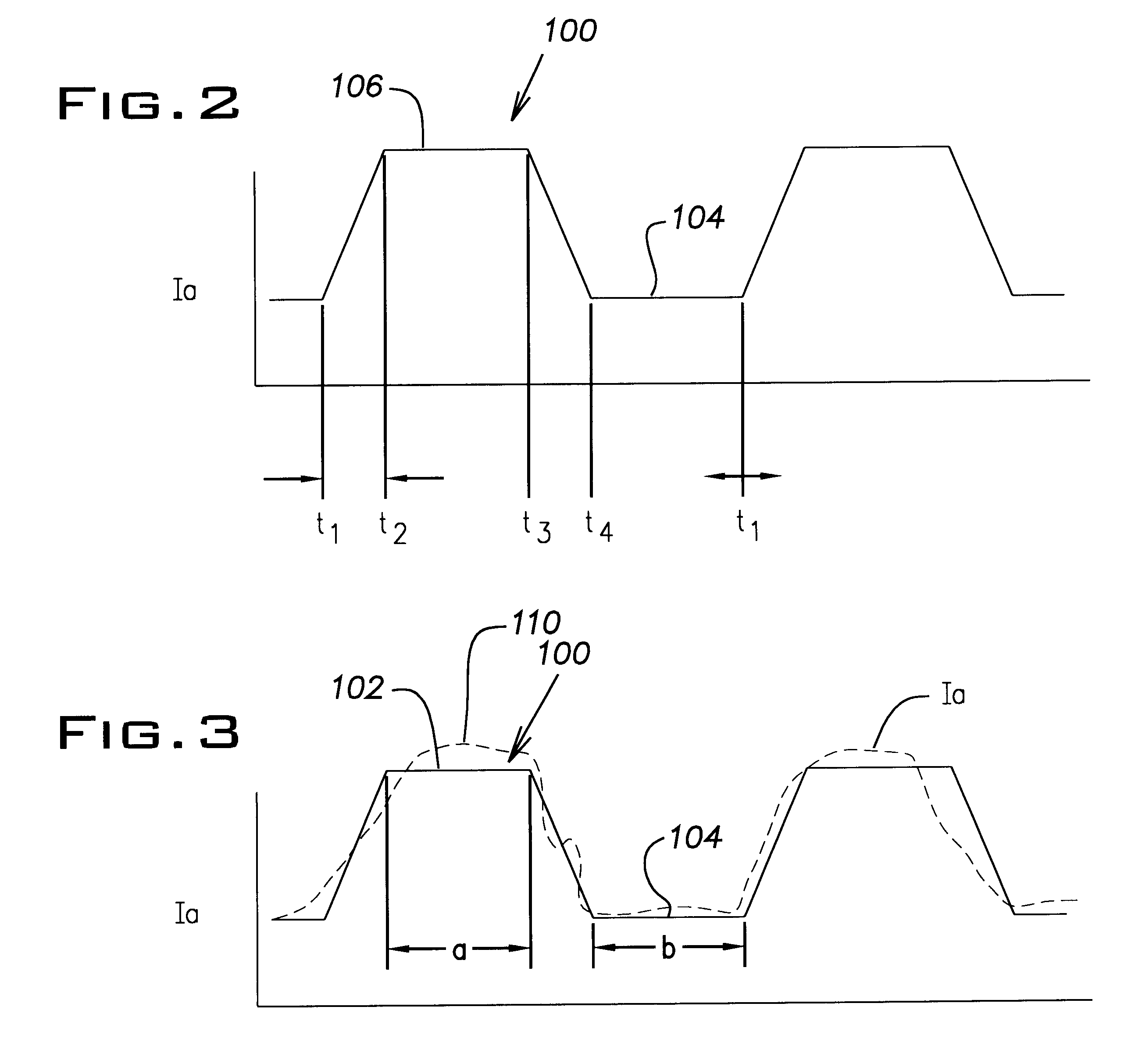
arc stability. Monitoring background time at WFS1, or monitoring peak current at WFS2 in this example, would be very ineffective. It is new to use a
time segment of the
wave shape for monitoring only this segment of the wave shape using prior knowledge of the desired values. This allows actual monitoring of the electric
arc welding process and not merely an averaging over the total wave shape.
By using the present invention, production information over a
calendar time, shift or even by operator can be accumulated for the purposes of evaluating the operation or efficiency of a welder. The monitoring of each weld cycle by monitoring a specific segment or state of the wave shape allows accumulation of undesired events experienced over time. This also allows a
trend analysis so that the operator can take corrective actions before the
welding process actually produces defective production welds.
Trend analysis, defect analysis, accumulated defects,
logging of all of these items and related real time monitoring of the electric arc welder allows direct intervention in a timely manner to take preventive actions as opposed to corrective actions.
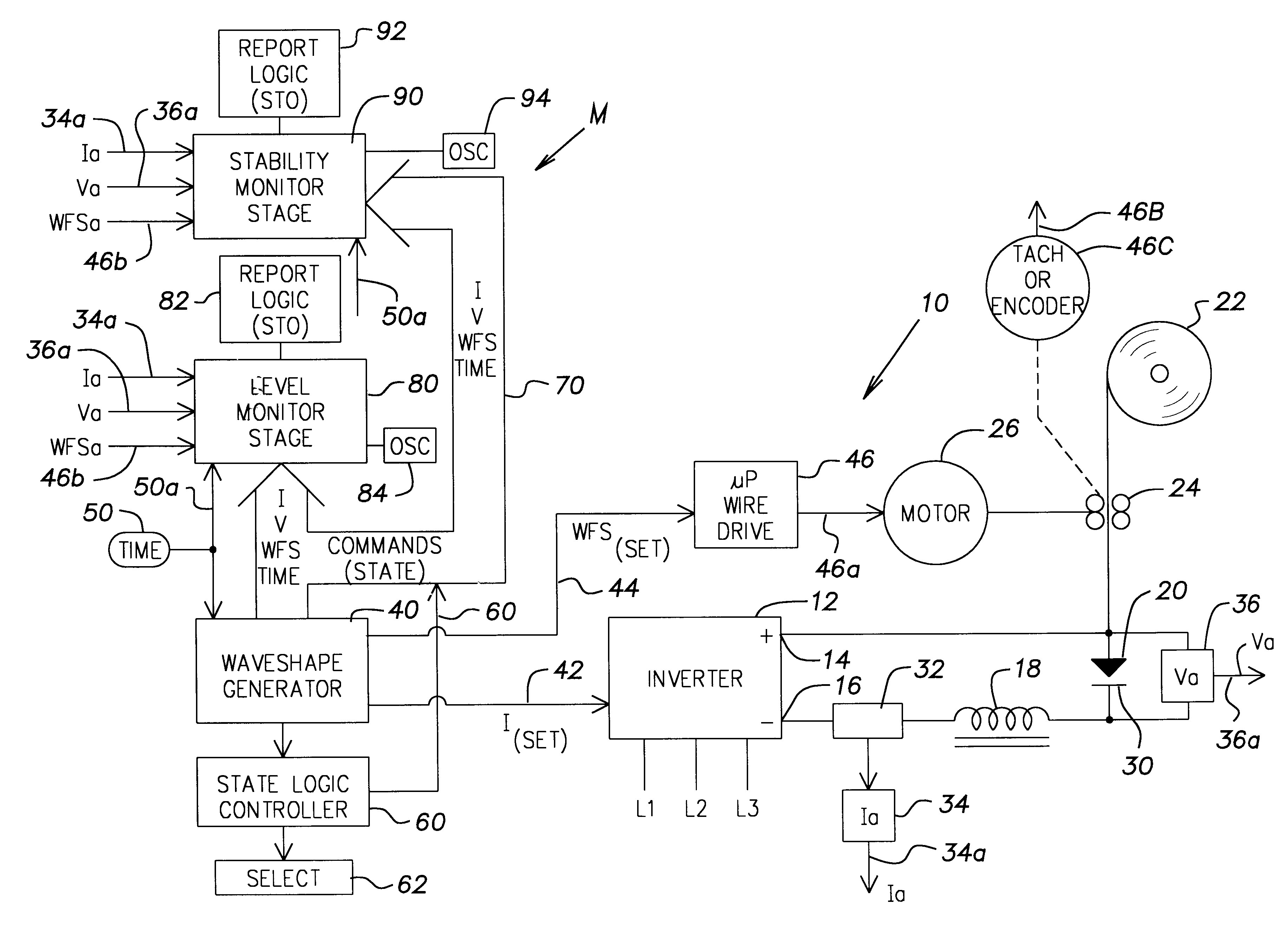
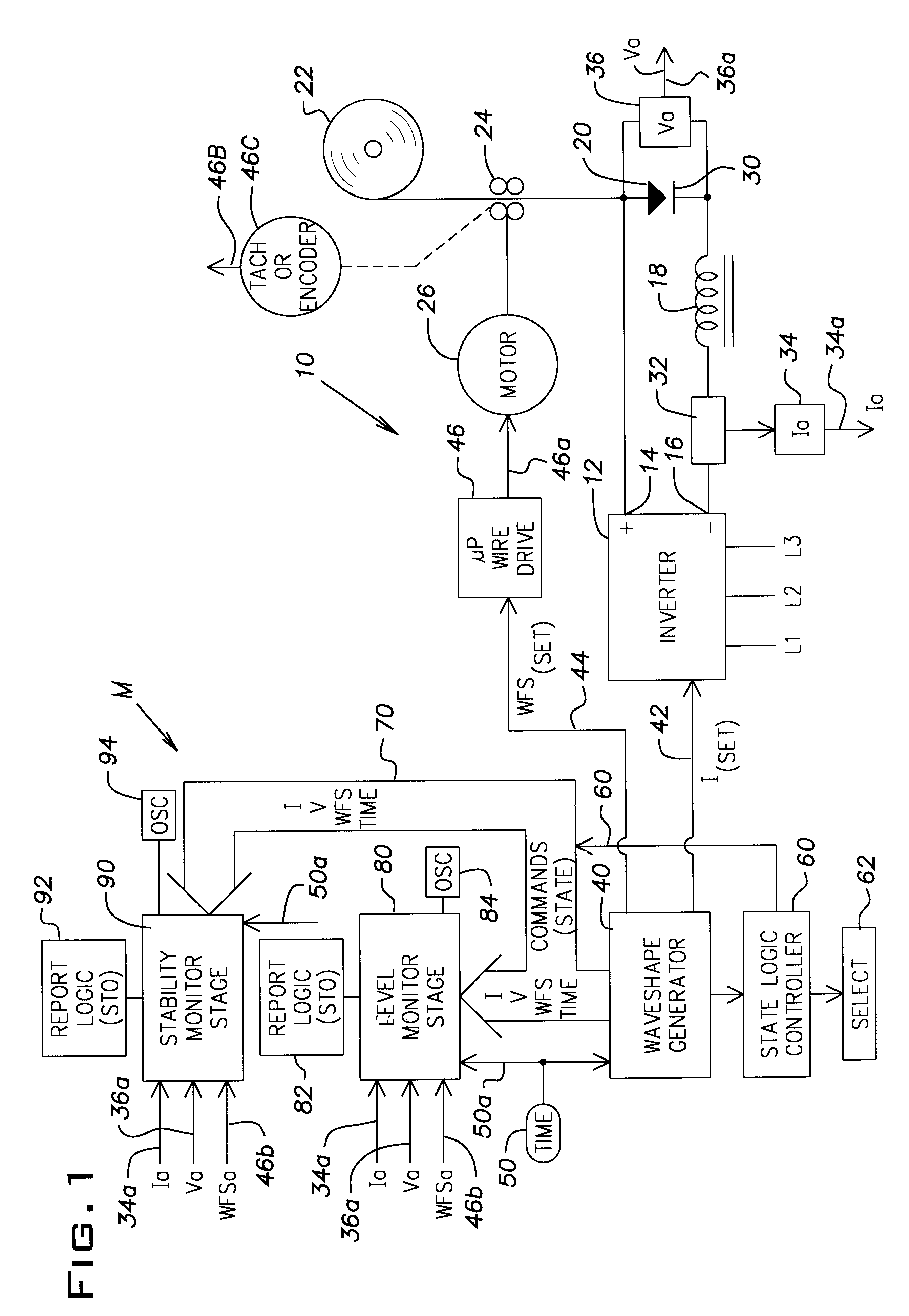
By using the present invention, the welder is commanded to create certain parameters at a certain level. The actual parameters are measured and compared to the threshold levels. Stability algorithms give a reading of stability. The output characteristics are generated for different states selected to be monitored. In the
computer program different characteristics for the selected states are analyzed and outputted or stored. The invention uses commanded wave shapes for the purposes of segmenting the monitored data. The known commanded behavior is compared to the observed behavior for analysis by the monitor. Consequently, data segmentation of the wave shape reduces the
chaotic output information heretofore obtained in monitors for electric arc welders. The data is obtained at a rate of at least about 1.0 kHz. In certain instances, as explained earlier, the data is collected at a rate of 10-40 kHz. Due to this rapid
data acquisition rate, onboard
processing of the data is preferred. Thus, the electric arc welder outputs
hard copy or displaces on a screen the information processed by the monitor. The monitor uses a digital process device, such as a computer or
microprocessor associated with the welder and having sufficient memory to store the information or to output statistical summaries of the information upon request. Such statistical summaries may be available rapidly or on an inquiry basis. By using prior knowledge and determining
arc stability and performance, anticipated problems are avoided by correcting the
welding process before defective welding is experienced.
The primary parameters monitored by the present invention are time, arc current,
arc voltage and global scale factor. These parameters are analyzed for the purposes of stability over a total weld cycle on an average basis or on a stability basis. A minimum level and a
maximum level monitoring is conducted by using the present invention. Although the total weld cycle of rapidly repeating wave shapes is monitored, the actual monitoring process is performed on a selected portion of each weld shape. By focusing on the individual states, in a total weld shape, variations during the selected state provide extremely high sensitivity and tremendously high level of real time knowledge and data.
Still another object of the present invention is the provision of a monitor and
monitoring system for an electric arc welder, which monitor and
monitoring system monitors precise portions of the wave shapes used to control the welder. Thus, the monitor accuracy is drastically increased since it contains substantial
real time data based upon prior knowledge.

