Dynamic granular memory power gating for hardware accelerators

a technology of granular memory and accelerator, applied in the field of hardware accelerators, can solve the problems of reducing the leakage power of the accelerator, affecting the processing efficiency of photographical data such as photos or videos, and consuming significant amounts of memory by the neural network

Active Publication Date: 2022-07-12
APPLE INC
View PDF19 Cites 0 Cited by
  • Summary
  • Abstract
  • Description
  • Claims
  • Application Information

AI Technical Summary

Benefits of technology

[0004]In one embodiment, a local memory that is dedicated to one or more hardware accelerators is divided into a plurality of independently powerable sections. That is, one or more of the sections may be powered on while other ones within the plurality of sections are powered off. The hardware accelerators receive instruction words from one or more central processing units (CPUs). The instruction words may include a field that specifies an amount of the memory that is used when processing the first instruction word, and the power control circuit may be configured to power a subset of the plurality of sections to provide sufficient memory for the instruction word based on the field, while one or more of the plurality of sections are powered off. A larger memory may be supported, and the portion that is used for processing each instruction word may be powered on while powering off the remainder of the local memory, reducing leakage power in some embodiments.

Problems solved by technology

In many cases, the accelerators can operate on large data sets that present a significant “footprint” in the memory of the system.
For example, neural networks often consume significant amounts of memory, and are also frequently implemented in hardware accelerators.
As another example, processing of photographical data such as photos or videos may be accelerated and may consume significant amounts of memory, especially when higher resolution images are processed.
Accelerators that operate on large data sets often consume more power moving data back and forth to system memory than they consume in computation.
However, larger local memories also typically have higher leakage power, contributing to power consumption attributable to the accelerator.

Method used


Image

  • Dynamic granular memory power gating for hardware accelerators
  • Dynamic granular memory power gating for hardware accelerators
  • Dynamic granular memory power gating for hardware accelerators

Examples


Embodiment Construction

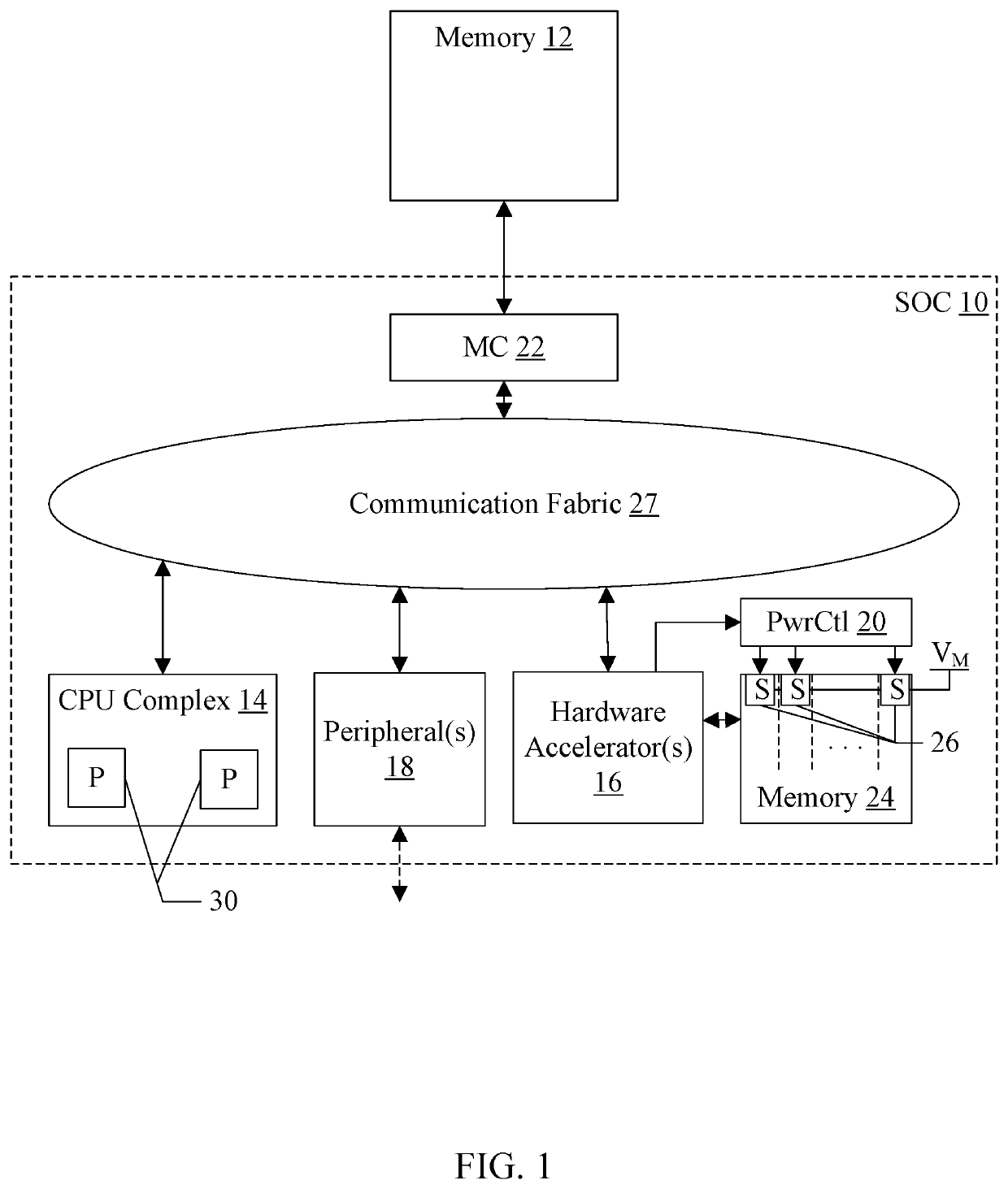
[0029]Turning now to FIG. 1, a block diagram of one embodiment of an SOC 10 is shown coupled to a memory 12. As implied by the name, the components of the SOC 10 may be integrated onto a single semiconductor substrate as an integrated circuit “chip.” In some embodiments, the components may be implemented on two or more discrete chips in a system. However, the SOC 10 will be used as an example herein. In the illustrated embodiment, the components of the SOC 10 include a central processing unit (CPU) complex 14, one or more peripheral components 18 (more briefly, “peripherals”), a memory controller 22, one or more hardware accelerators 16, a power control circuit 20, a local memory 24, and a communication fabric 27. The components 14, 16, 18, and 22 may all be coupled to the communication fabric 27. The memory controller 22 may be coupled to the memory 12 during use. The hardware accelerator 16 is coupled to the power control circuit 20, both of which are coupled to the memory 24.

[003...


PUM


Abstract

In an embodiment, a local memory that is dedicated to one or more hardware accelerators is divided into a plurality of independently powerable sections. That is, one or more of the sections may be powered on while other ones of the plurality of sections are powered off. The hardware accelerators receive instruction words from one or more central processing units (CPUs). The instruction words may include a field that specifies an amount of the memory that is used when processing the first instruction word, and the power control circuit may be configured to power a subset of the plurality of sections to provide sufficient memory for the instruction word based on the field, while one or more of the plurality of sections are powered off.

Description

BACKGROUNDTechnical Field[0001]Embodiments described herein are related to hardware accelerators in digital systems that include local memory.Description of the Related Art[0002]Hardware accelerators can be included in various computing systems to perform specific tasks at higher performance and / or higher efficiency than can typically be achieved in software executing on processors in the system (e.g. on central processing units, or CPUs, in the system). In many cases, the accelerators can operate on large data sets that present a significant “footprint” in the memory of the system. For example, neural networks often consume significant amounts of memory, and are also frequently implemented in hardware accelerators. As another example, processing of photographical data such as photos or videos may be accelerated and may consume significant amounts of memory, especially when higher resolution images are processed.[0003]Accelerators that operate on large data sets often consume more p...

Claims


Application Information

Patent Timeline
Patent Type & Authority Patents(United States)
IPC IPC(8): G06F1/00G06F1/26G06F9/30G06F1/3203
CPCG06F1/26G06F9/30043G06F1/3203G06F9/3881G06F9/30185G06F1/3228G06F1/3275G06F1/3243Y02D10/00Y02D30/50
Inventor DI FEBBO, PAOLORAJAN, YOHANVIDANAGAMACHCHI, CHAMINDA NALAKA
Owner APPLE INC
Why Eureka
Try Eureka