Hydraulic braking system for automobiles

Inactive Publication Date: 2002-09-10
ROBERT BOSCH GMBH
View PDF2 Cites 76 Cited by
  • Summary
  • Abstract
  • Description
  • Claims
  • Application Information

AI Technical Summary

Problems solved by technology

Due to their oscillating operation, piston pumps have an oscillating intake volume flow and cause pressure pulsations on the intake side, which have repercussions on the master cylinder and produce an unpleasant s

Method used


Image

  • Hydraulic braking system for automobiles
  • Hydraulic braking system for automobiles
  • Hydraulic braking system for automobiles

Examples


Embodiment Construction

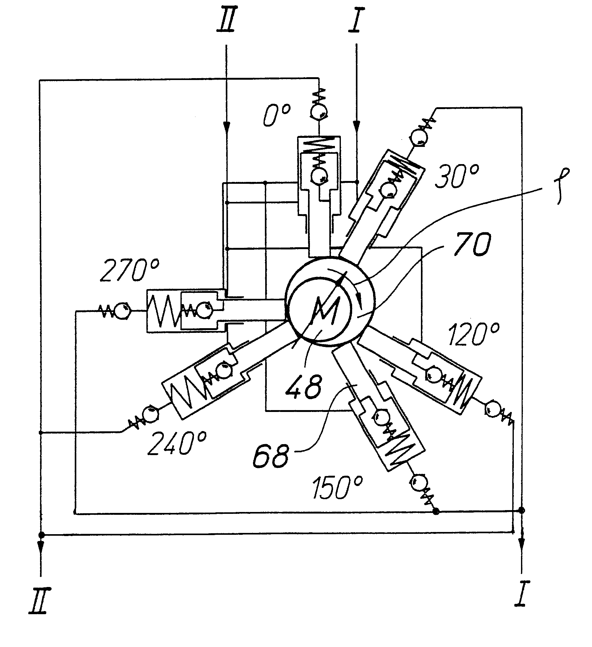
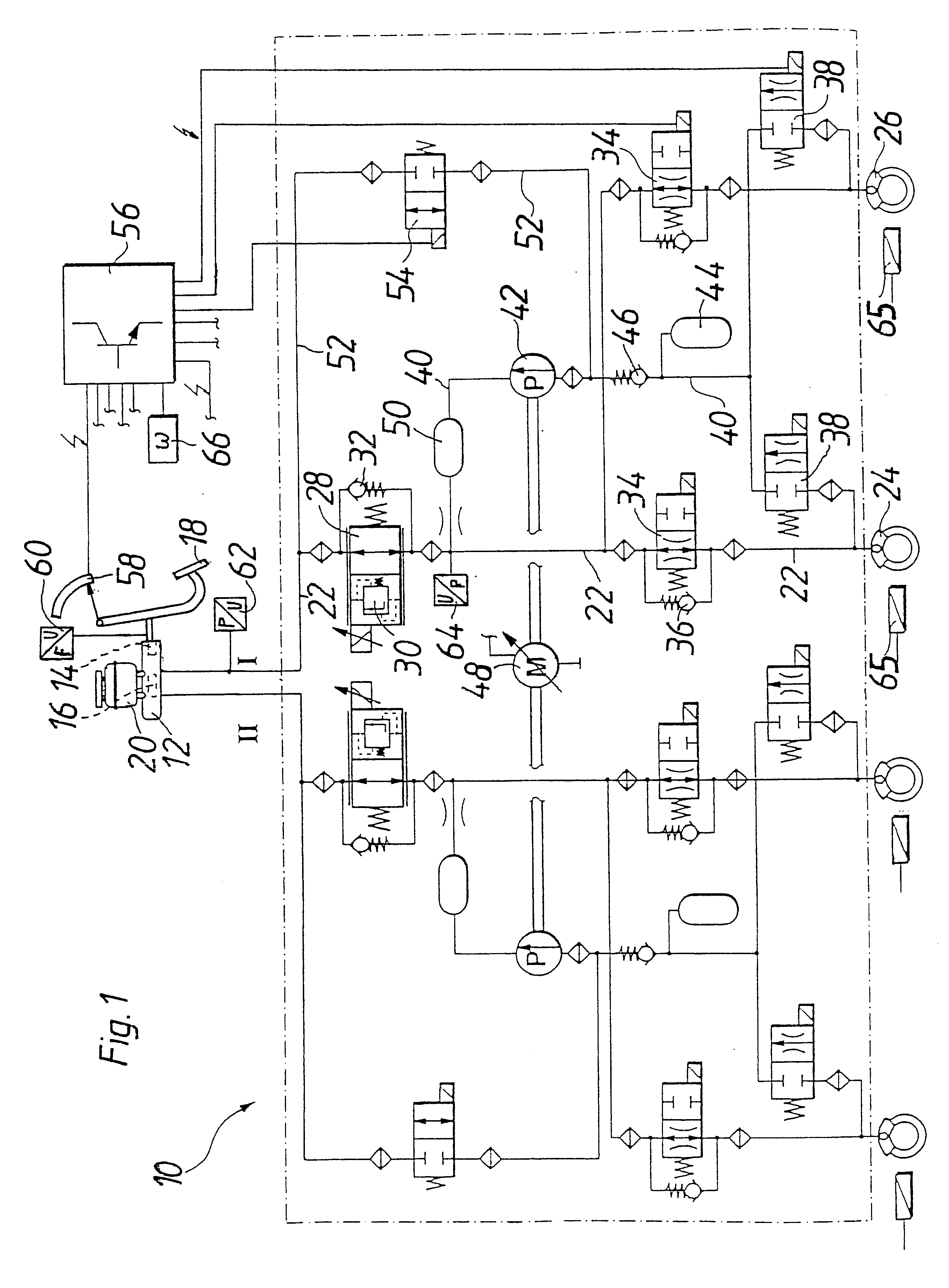
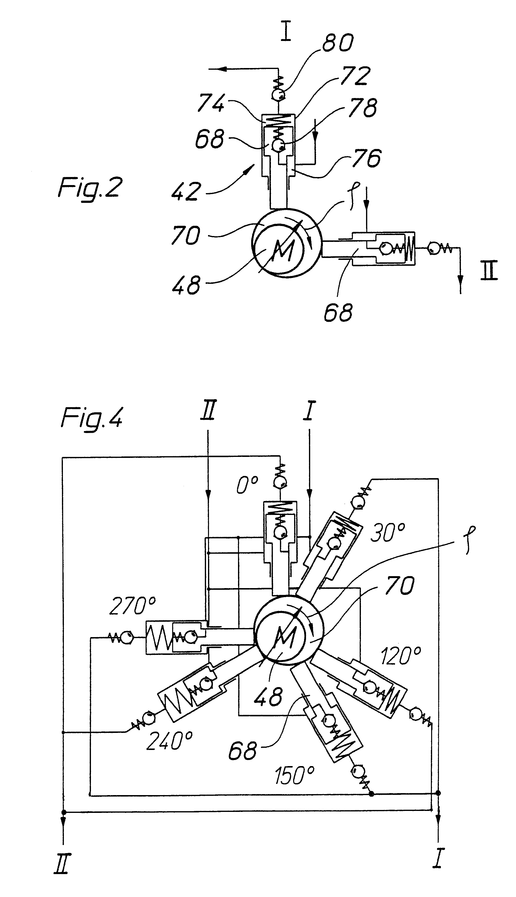
The vehicle hydraulic brake system 10 according to the invention shown in FIG. 1 is embodied as a dual-circuit brake system which has two brake circuits I, II that are independent of each other. The brake circuits I, II are connected to a dual-circuit master cylinder 12, which in an intrinsically known manner has a rod piston 14 and a floating piston 16, which are indicated with dashed lines. The rod piston 14 is actuated directly by a foot brake pedal 18, the floating piston 16 is acted on by the pressure produced by the rod piston 14 and as a result, likewise produces a brake pressure in the second brake circuit II. Furthermore, the master cylinder 12 has a brake fluid reservoir 20.

The two brake circuits I, II are correspondingly embodied and function in the same manner. The two brake circuits I, II will be described below in conjunction with the brake circuit I shown on the right in FIG. 1. A main brake line 22 leads from the master cylinder 12 to two wheel brake cylinders 24, 26...


PUM


Abstract

The invention relates to a vehicle hydraulic brake system with electrohydraulic brake boosting by a piston pump. In order to reduce pressure pulsations on an intake side of the multi-piston pump, the brake system embodies a multi-piston pump, for example, as a six-piston pump with stepped pistons that are driven with an alternating phase shift of 30° and 90° in relation to one another. The phase shift of the drive of the stepped pistons is selected so that the intake volume flows have a uniform phase shift, by which the total intake volume flow of the multi-piston pump has a reduced amplitude of the pressure pulsation, which reduces the repercussions on a master cylinder.

Description

PRIOR ARTThe invention relates to a vehicle hydraulic brake systemA vehicle hydraulic brake system of this kind has been disclosed by DE 195 01 760 A1. The known vehicle brake system has a master cylinder, a number of wheel brake cylinders, and a hydraulic pump with which brake fluid can be delivered from the master cylinder to the wheel brake cylinders. The hydraulic pump is used for hydraulic brake boosting. It can likewise be used for antilock braking, traction control, and electronic stability programming, wherein in order to reduce pressure in the wheel brake cylinders by way of valves, the intake side of the hydraulic pump can be connected to the wheel brake cylinders and the pressure side of the hydraulic pump can be connected to the master cylinder. It is conventional per se to embody the hydraulic pumps in vehicle brake systems of this kind as dual piston pumps with pistons disposed opposite each other in a boxer arrangement, which are driven by a common cam disposed betwee...

Claims


Application Information

Patent Timeline
IPC IPC(8): B60T8/40B60T13/68B60T17/02B60T17/00B60T8/48F04B11/00
CPCB60T13/686B60T17/02F04B11/005B60T8/4031B60T8/4872B60T8/40
Inventor WILLMANN, KARL-HEINZBAUMANN, DIETMARHAAS, HARDYSCHMIT, STEPHANEVOLLERT, HERBERTREPPICH, ANDREAS
Owner ROBERT BOSCH GMBH
Why Eureka
Try Eureka