Diffraction grating for wavelength division multiplexing/demultiplexing devices

a diffraction grating and wavelength division technology, applied in the direction of mountings, optics, instruments, etc., can solve the problems of channel uniformity simply not being maintained, insertion loss will continue to increase, and many difficulties of thin film filtering based multiplexing/demultiplexing devices

Inactive Publication Date: 2002-09-10
AUXORA
View PDF12 Cites 87 Cited by
  • Summary
  • Abstract
  • Description
  • Claims
  • Application Information

AI Technical Summary

Benefits of technology

FIG. 5 is a plot showing the effect of the thickness ratio of the glass cover and the glass substrate on grating warping in accordance with the present invention.

Problems solved by technology

However, there are many difficulties associated with thin film filtering based multiplexing / demultiplexing devices.
However, due to the cascade configuration typically associated with thin film filtering based multiplexing / demultiplexing devices, channel uniformity simply cannot be maintained.
That is, insertion losses will continually increase as light continues to be transmitted through each individual thin film filter.
However, AWG based multiplexing / demultiplexing devices still suffer from several intrinsic disadvantages such as high insertion loss, high channel crosstalk, and active temperature control.
For example, although some recent laboratory experiments on AWG based multiplexing / demultiplexing devices have achieved insertion losses as low as 0.8 dB (on the chip level), commercially available AWG based multiplexing / demultiplexing devices still only achieve insertion losses on the order of 5-6 dB.
However, thermal instability and narrow channel passband are two major drawbacks which prevent bulk diffraction grating based multiplexing / demultiplexing devices from prevailing over other types of multiplexing / demultiplexing devices.
As can be seen from FIGS. 2 and 3, bulk diffraction grating based multiplexing / demultiplexing devices are extremely temperature sensitive.

Method used


Image

  • Diffraction grating for wavelength division multiplexing/demultiplexing devices
  • Diffraction grating for wavelength division multiplexing/demultiplexing devices
  • Diffraction grating for wavelength division multiplexing/demultiplexing devices

Examples


Embodiment Construction

)

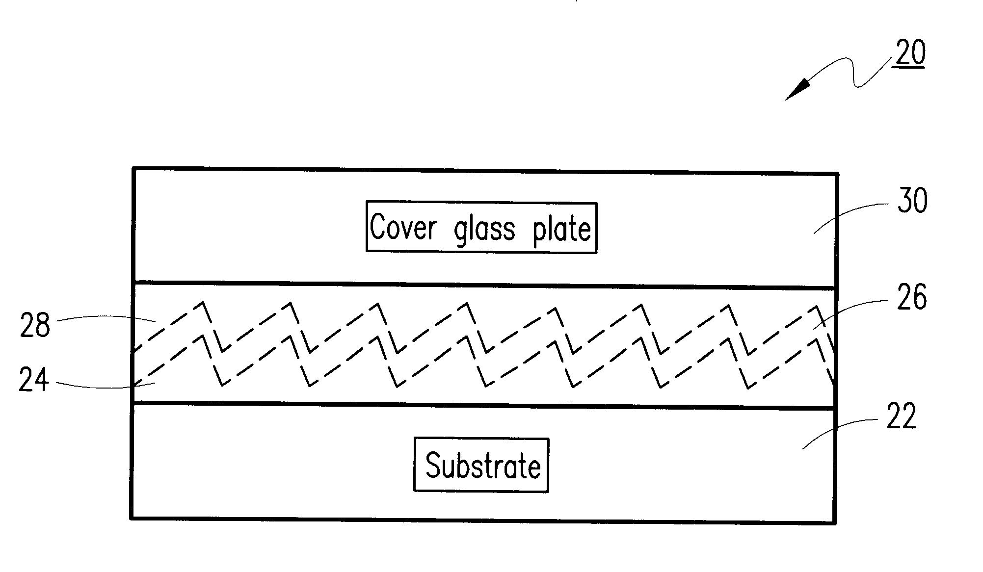
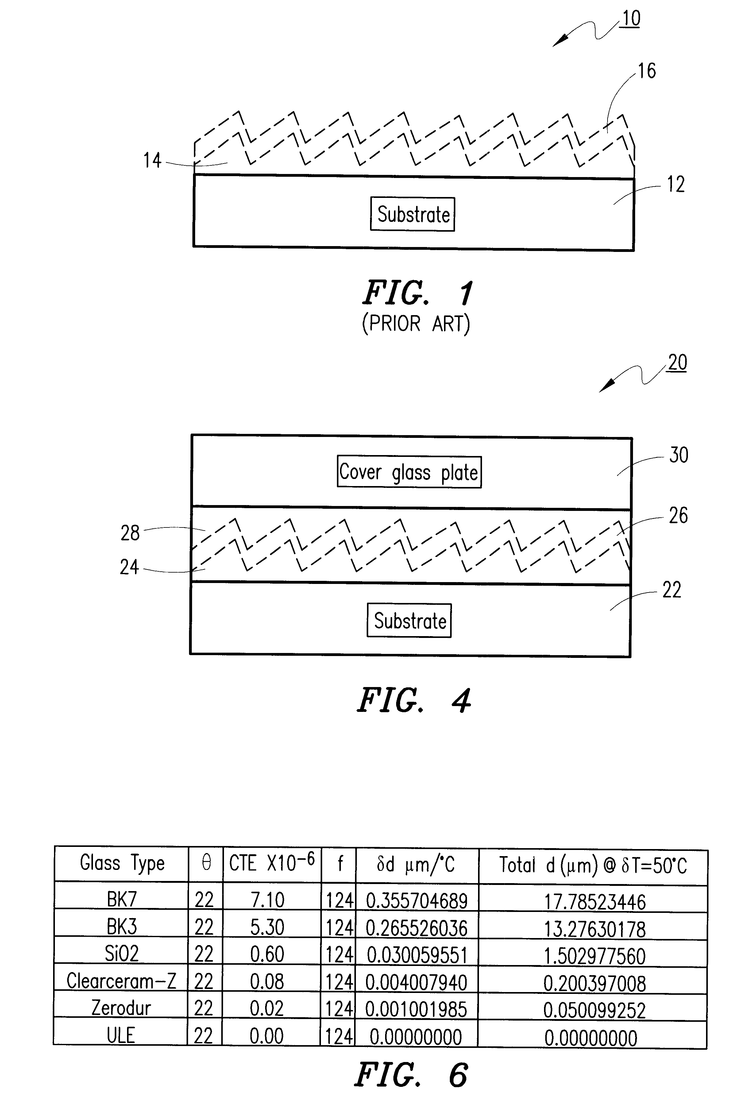
Referring to FIG. 4, there is shown an improved diffraction grating 20 for use in a bulk diffraction grating based multiplexing / demultiplexing device in accordance with the present invention. The improved diffraction grating 20 comprises a glass substrate 22, a polymer grating layer 24 located adjacent to the glass substrate 22, a metal coating layer 26 located adjacent to the polymer grating layer 24, a polymer coating layer 28 located adjacent to the metal coating layer 26, and a glass cover 30 located adjacent to the polymer coating layer 28. The metal coating layer 26, which is used to increase the reflectivity of the improved diffraction grating 20, is typically formed of gold (Au) or aluminum (Al) and typically has a thickness in the range of 0.05 to 0.5 .mu.m.

With the basic structure of the improved diffraction grating 20 now described, important characteristics of the improved diffraction grating 20 will now be discussed. That is, while the present invention centers around ...


PUM

PropertyMeasurementUnit
thicknessaaaaaaaaaa
thicknessaaaaaaaaaa
insertion lossesaaaaaaaaaa

Abstract

An improved diffraction grating for wavelength division multiplexing/demultiplexing devices is disclosed. The improved diffraction grating has a glass substrate, a polymer grating layer located adjacent to the glass substrate, and a metal coating layer located adjacent to the polymer grating layer. The improvement comprises a polymer coating layer located adjacent to the metal coating layer, and a glass cover located adjacent to the polymer coating layer, wherein the polymer coating layer and the glass cover compensate for thermal characteristics associated with the polymer grating layer and the glass substrate, respectively.

Description

The present invention relates generally to wavelength division multiplexing and, more particularly, to an improved diffraction grating for wavelength division multiplexing / demultiplexing devices.Currently, approximately 70% of the wavelength division multiplexing (WDM) market in the United States utilize thin film filtering based multiplexing / demultiplexing devices. However, there are many difficulties associated with thin film filtering based multiplexing / demultiplexing devices. For example, for high channel count (i.e., 32 plus channels) multiplexing / demultiplexing devices, channel uniformity is important. However, due to the cascade configuration typically associated with thin film filtering based multiplexing / demultiplexing devices, channel uniformity simply cannot be maintained. That is, insertion losses will continually increase as light continues to be transmitted through each individual thin film filter.Recently, multiplexing / demultiplexing devices incorporating array wavegu...

Claims


Application Information

Patent Timeline
Patent Type & Authority Patents(United States)
IPC IPC(8): G02B5/18G02B6/34G02B7/00
CPCG02B5/1861G02B7/008G02B6/29398Y10S359/90
Inventor ZHU, NINGHUITURNER, IANYUDIN, YURI A.SOKOLSKIY, MIKHAIL N.WADE, ROBERT K.
Owner AUXORA
Why Eureka
Try Eureka