
Apparatus and method for changing flexible printing plates

a flexible printing plate and apparatus technology, applied in printing presses, office printing, printing, etc., can solve the problems of insufficient maintenance work on the plate cylinder, insufficient distance of the device from the plate cylinder, and restricted access to the plate cylinder

Inactive Publication Date: 2002-09-17
MANROLANAD AG
View PDF5 Cites 15 Cited by
  • Summary
  • Abstract
  • Description
  • Claims
  • Application Information

AI Technical Summary

Benefits of technology

A significant advantage of the present invention is that it provides the required functional elements, in a small space, in an apparatus which is of simple construction and is easy to handle.
It is a further object of the present invention to avoid the necessity of using additional bulky devices. To this end, a separate pressure roll is not required for the printing plate. Specifically, the apparatus of the present invention can be readily mounted in a pivotable frame and can therefore be moved completely away from the plate cylinder. This ensures accessibility of the plate cylinder for maintenance work.
A still further object of the present invention is to provide an effective means of moving the printing plates. According to the present invention, a further significant advantage is achieved in that the transporting means bears the holding means and is configured so that it is arranged between the magazines and the plate cylinder and can be pivoted. As a result, the holding means can grip both the printing plate to be inserted and the printing plate to be removed, and can guide them to and from the plate cylinder, respectively. Suitable holding means may, for example, be suction devices that can be loaded both with vacuum and with pressure by an air supply system.
A further advantage of the present invention is that the magazines are additionally arranged in a frame which can be moved by means of a drive device, so that both the magazine for the printing plate to be inserted into the plate cylinder and the magazine for holding the printing plate to be removed from the plate cylinder can be set against the holding means.
A further significant advantage arises in that the drive device used to pivot the entire apparatus can also perform both an insertion movement of the leading end of the printing plate to inserted into a channel of the plate cylinder, and a removal movement of the trailing end of the printing plate to be removed from the channel in the plate cylinder.
The present invention also relates to a method for changing flexible printing plates on a plate cylinder of a printing machine providing an easy way to change printing plates.

Problems solved by technology

The disadvantage of this configuration is that accessibility to the plate cylinder is very restricted, since the working cylinders that pivot the devices for feeding the printing plate and removing it are arranged so that they cross in the drive-side frame side wall.
In addition, in this type of an arrangement, the space below the pivoting devices is small, so that the distance of the devices from the plate cylinder, after they have been pivoted away into a park position, is not sufficient to perform maintenance work on the plate cylinder without being a physical hindrance.
A further configuration of the prior art makes access to the plate cylinder difficult, in that in order to change the printing plates, pressure rollers with actuating rollers which can be set against the plate cylinder are required.
A further disadvantage of DE 43 22 027 A1 is apparent when separating the printing plate to be removed from the plate cylinder.
The disadvantage of this configuration is that the displaceable carriage in the apparatus for changing plates is relatively high, which contrasts with the low space available in rotary printing machines.
The disadvantage of this configuration is that since the transporting means is between the magazines the apparatus is relatively high.
As a result, already restricted space between the printing units is further limited, further impeding accessibility to the plate cylinder.
A further disadvantage of DE 195 08 844 C2 is that although there is a transporting means to transport the printing plate to be inserted and removed, suction devices facing the printing plate are required on the transporting means in order to guide and grip the printing plate.
This further interferes with a compact overall height and also increases the costs of the apparatus.

Method used


Image

  • Apparatus and method for changing flexible printing plates
  • Apparatus and method for changing flexible printing plates
  • Apparatus and method for changing flexible printing plates

Examples


Embodiment Construction

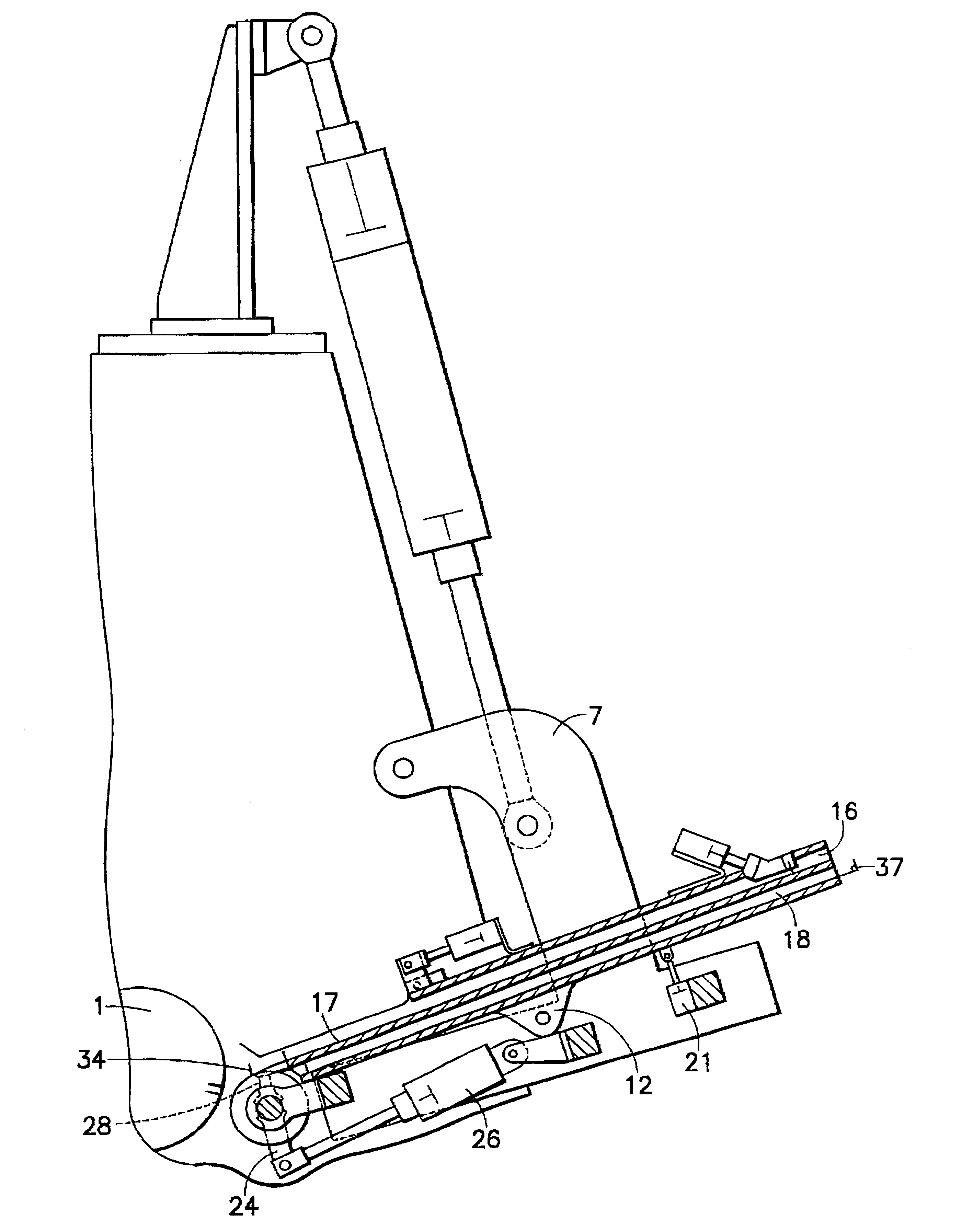
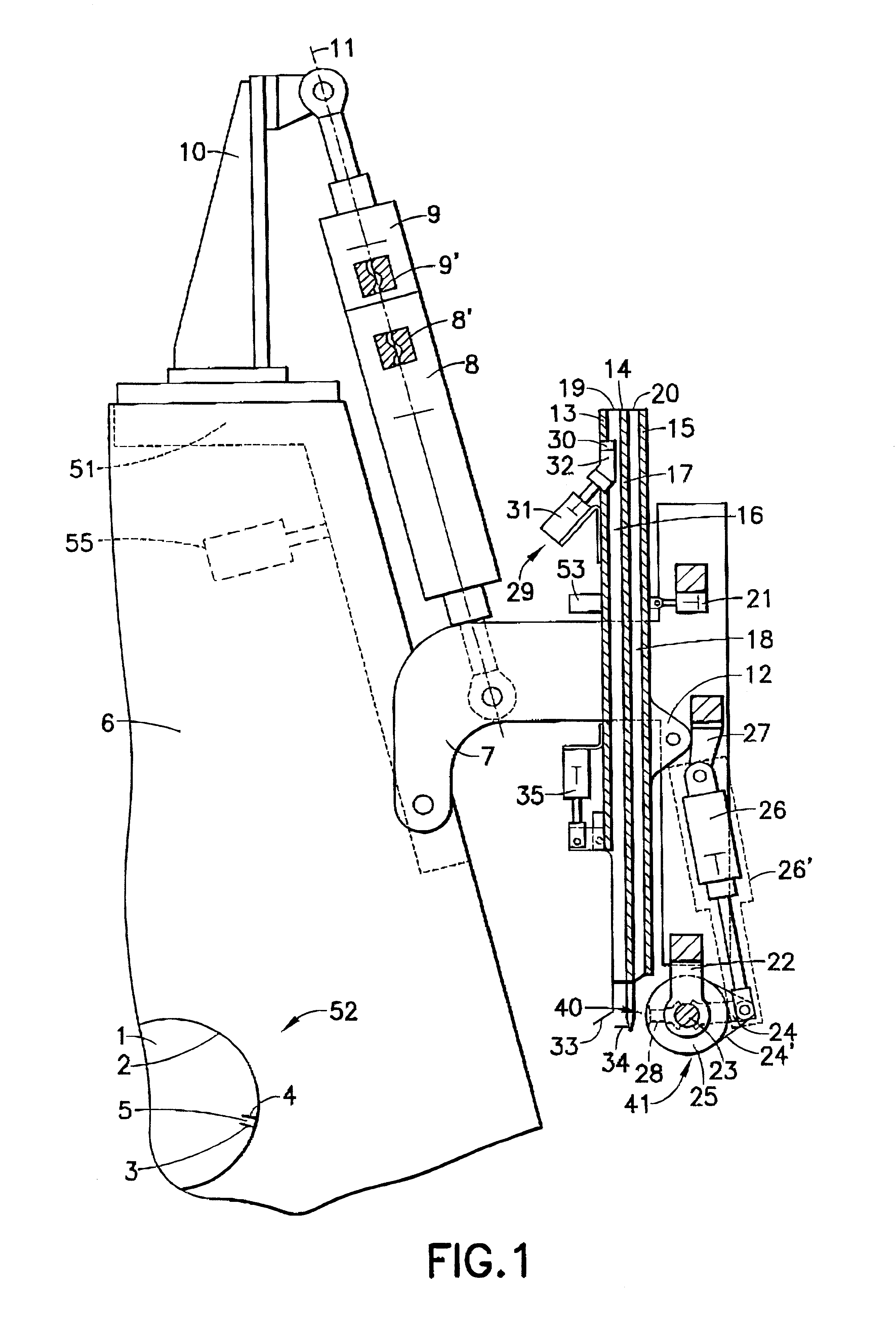
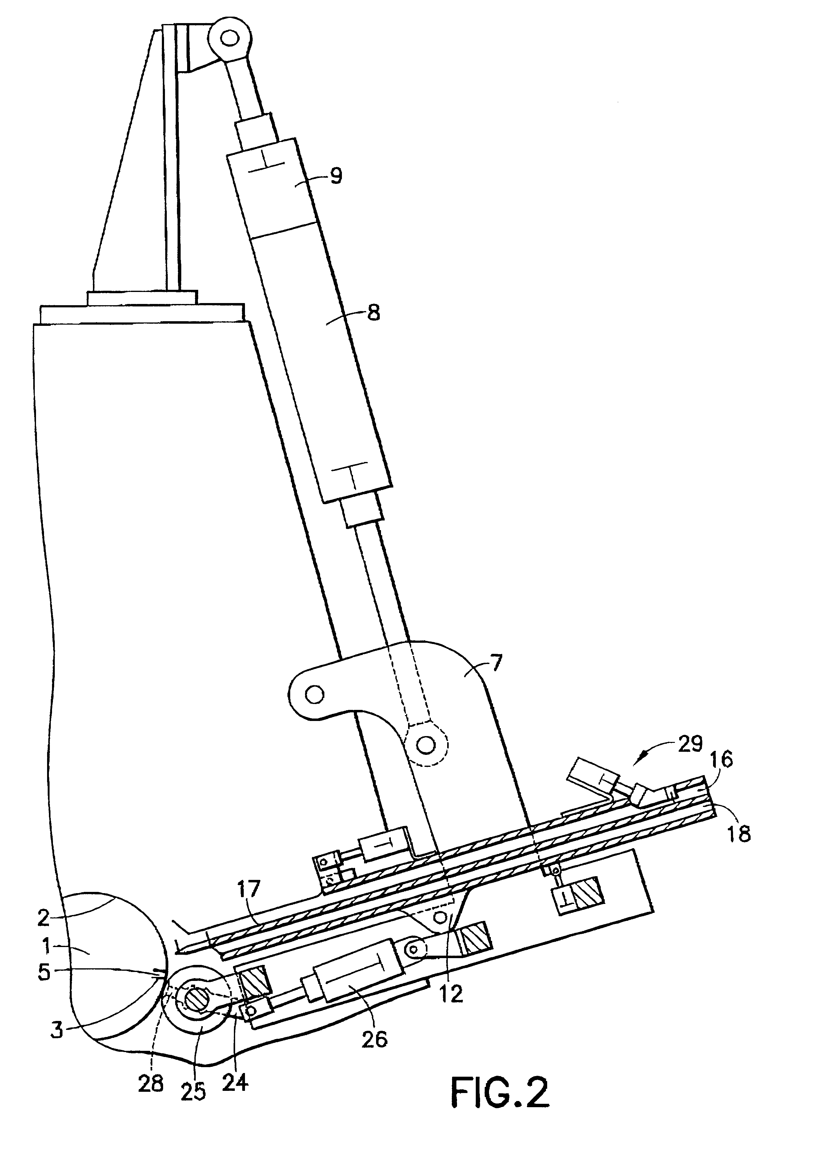
Referring now to FIG. 1, a plate cylinder 1 is shown on the circumference of which is clamped a flexible printing plate 2, the bent end 3 of which trails in the direction of rotation of the plate cylinder 1. A leading bent end 4 of the flexible printing plate 2 is inserted into a radial channel 5 in the plate cylinder 1 and secured against sliding out of the channel inadvertently. The plate cylinder 1 is mounted in a conventional way between frame walls 6 in a printing machine. In order to change the printing plate on the plate cylinder 1, there is an apparatus including a frame 7 mounted so that it can be pivoted on the frame wall 6. The apparatus is pivoted by means of two working cylinders 8, 9. The pivoting can alternatively be carried out by an electromechanical motor or a screw and nut drive which are generically indicated as 8', 9'. The construction of such motors and drives is known to those skilled in the art. One working cylinder 8 is rotatably mounted on the frame 7 and l...


PUM


Abstract

An apparatus for changing flexible printing plates on a plate cylinder of printing machines having a simple, compact and space-saving construction is provided. The apparatus includes two magazines arranged beside each other, to hold the printing plates to be inserted and removed. A transporting arrangement pivotably mounted on a shaft is beside the magazines. A holding arrangement which is on the transporting means is used both to grip and guide a printing plate to be inserted and to grip and guide a printing plate to be removed. The magazines and the transporting arrangement are mounted in a frame that can be pivoted towards and away from the plate cylinder. The invention further relates to a method of changing flexible printing plates on a plate cylinder of a printing machine.

Description

1. Field of the InventionThe present invention relates to an apparatus for changing flexible printing plates on a plate cylinder of a printing machine. More particularly the present invention relates to an apparatus including two adjacent magazines for two respective printing plates, a transporting arrangement beside the magazines, and a holding means for gripping and gliding the printing plates. The apparatus allows for ready access to the plate cylinder for maintenance and the like.2. Description of the Related ArtGerman reference DE 43 22 027 A1 discloses an apparatus for changing printing plates on a plate cylinder of a rotary printing machine, including devices for inserting and removing the print plate arranged so that they can be pivoted with respect to the plate cylinder. The disadvantage of this configuration is that accessibility to the plate cylinder is very restricted, since the working cylinders that pivot the devices for feeding the printing plate and removing it are a...

Claims


Application Information

Patent Timeline
IPC IPC(8): B41F27/12
CPCB41F27/1206B41P2227/60
Inventor KOPPELKAMM, GUNTERDUNGER, MATTHIASROTH, HEIKOHAMANN, REINER
Owner MANROLANAD AG
Learn More