
Tubing elongation correction system & methods

a technology of elongation correction and tube, which is applied in the field of tube elongation correction system & methods, can solve the problems of unintended violations of regulatory rules, rare, if ever profitable, and inability to recover water,

Inactive Publication Date: 2002-09-17
HALLIBURTON ENERGY SERVICES INC
View PDF4 Cites 38 Cited by
  • Summary
  • Abstract
  • Description
  • Claims
  • Application Information

AI Technical Summary

Benefits of technology

Reference length RL.sub.j provides a pre-determined and arbitrary reference point from which measured depth calculations can be made. Coiled tubing at the surface, prior to injection, is already exposed to factors such as ambient temperature (e.g., the temperatures of air and drilling fluid) and the hydraulic pressure of drilling fluid. The coiled tubing can also be exposed to axial forces (tension) induced by a number of elements including the operation of the injector, stripper, and tractor and tubing and BHA weight. These environmental factors will often change during well servicing operations and lengthen or shorten the tubing introduced into the well bore. Thus, two sections of coiled tubing, while having the same length when exposed to the same environmental profile, will cause a depth wheel to indicate different surface-measured lengths L.sub.j if there are differences in the environmental factors when these two coiled tubing sections are injected into the well bore. Routine 110 minimizes the errors caused by variation in surface environmental factors by converting all the surface-measured lengths L to theoretical reference lengths RL.

Problems solved by technology

This is even more the case with water layers because recovery of water is rarely, if ever, profitable.
Moreover, it is usually very undesirable to inadvertently drain a gas or water layer because these fluids tend to flood a well to such a degree that a well remains nonfunctional until all the water or gas has been evacuated from the well.
Further compounding the inherent difficulties in this situation is that, in many instances, a pay zone may be less than fifty feet in a well bore that may be thousands of feet in length.
Inaccurate data could lead to unintended violations of regulatory rules and subject the well owner to fines or other penalties.
While these prior art MD survey techniques may be reliable for tubing formed of metals such as steel, however, such techniques do not give accurate logs for tubulars made of materials such as composites.
Tubulars made of non-metals, such as composites, are susceptible to significant length changes due to factors such as temperature, pressure and axial loadings.
Unfortunately, elevated temperatures, high operating pressures and complex compression and tension loadings are almost always present in a well bore environment.
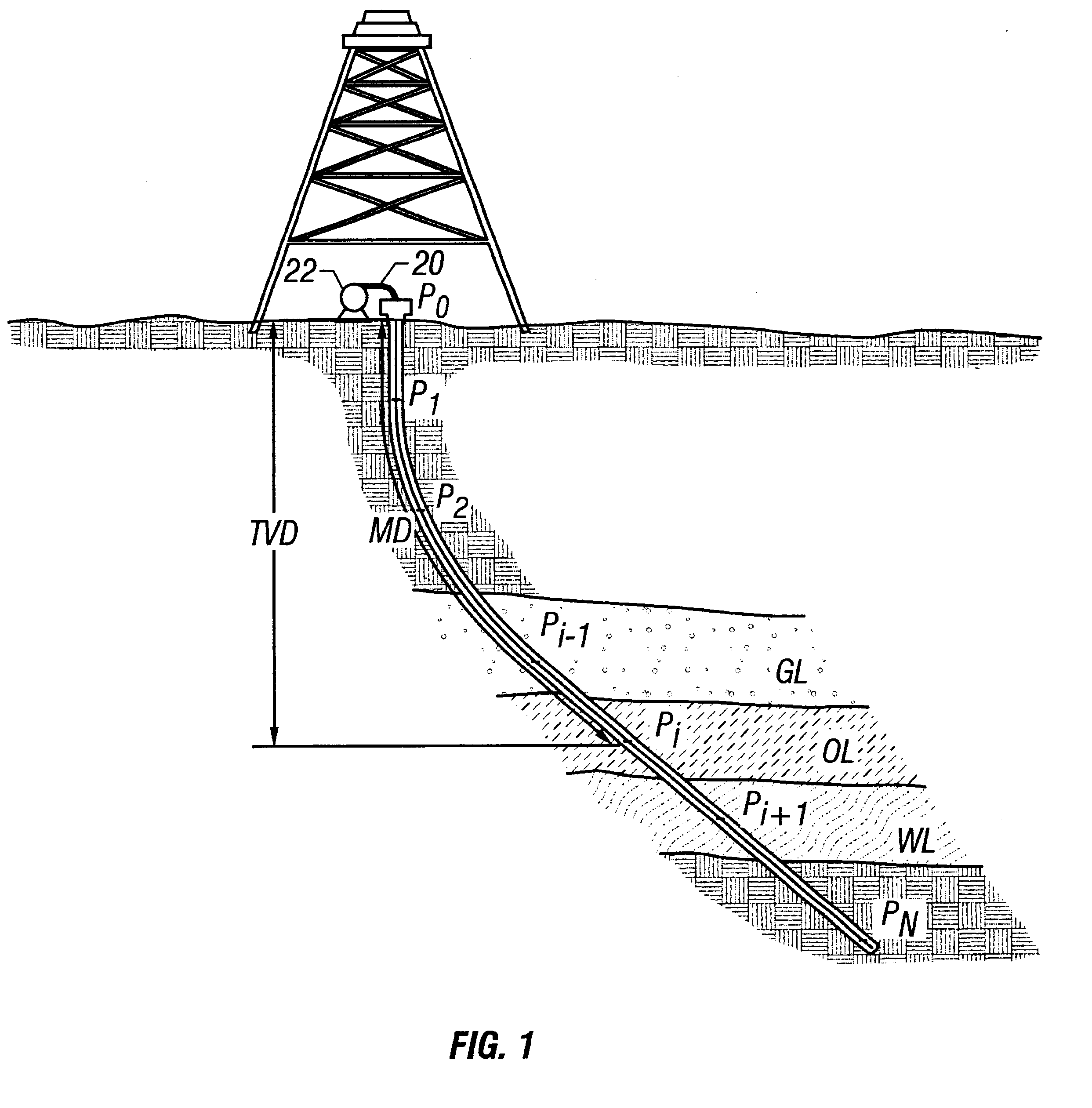
An uncorrected MD log can present serious problems in later operations when equipment such as perforation charges are tripped downhole to initiate the drainage of a pay zone at P.sub.i.
Indeed, even during successive composite coiled tubing trips for the same operation, downhole conditions can vary to a point where it may be difficult to correlate logs of these successive trips.
Despite the critical need for accurate MD logs, the prior art does not disclose systems or methods that correct surface measurements of tubulars made of materials that deform when exposed to environmental factors.

Method used


Image

  • Tubing elongation correction system & methods
  • Tubing elongation correction system & methods
  • Tubing elongation correction system & methods

Examples


Embodiment Construction

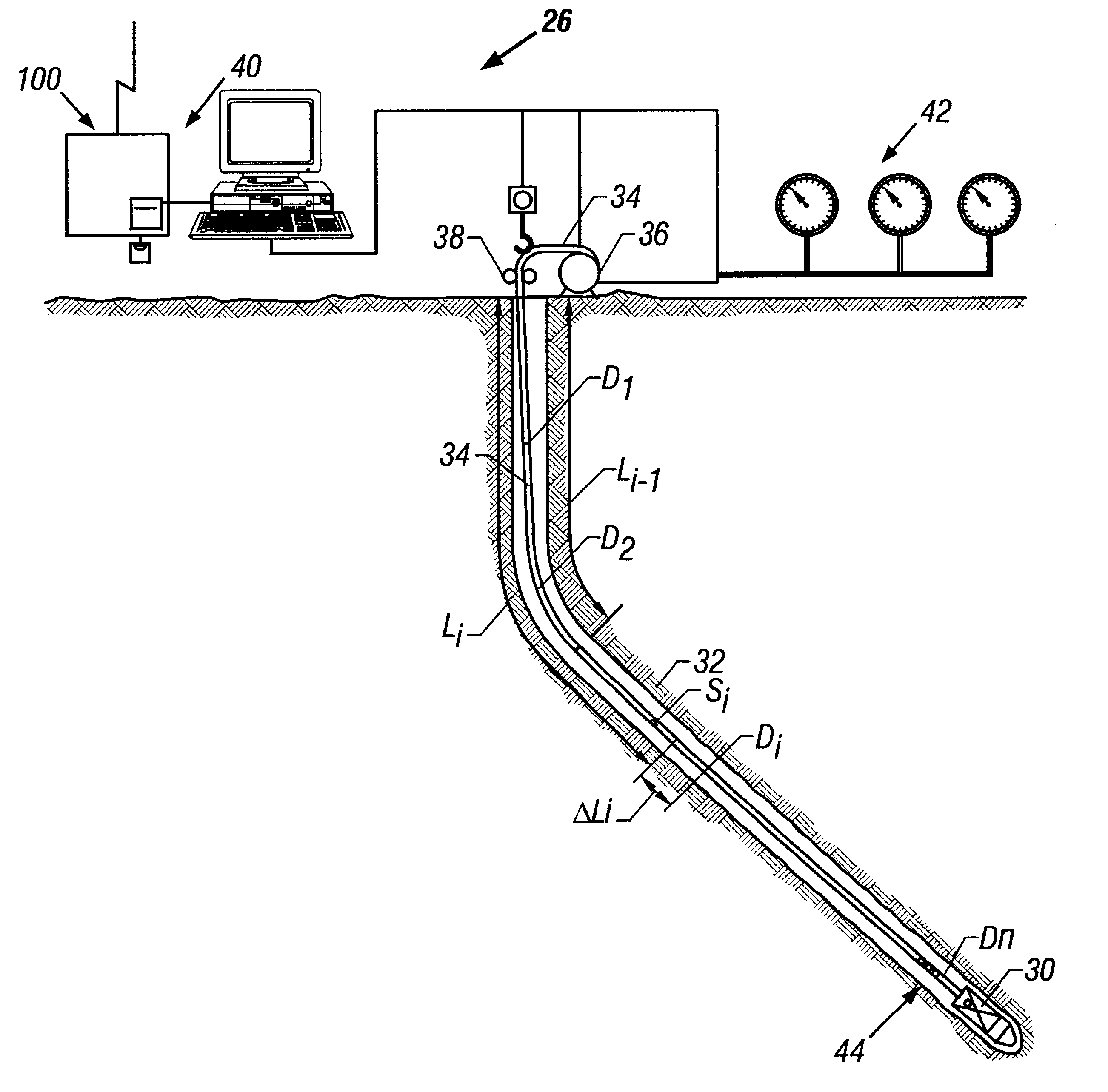
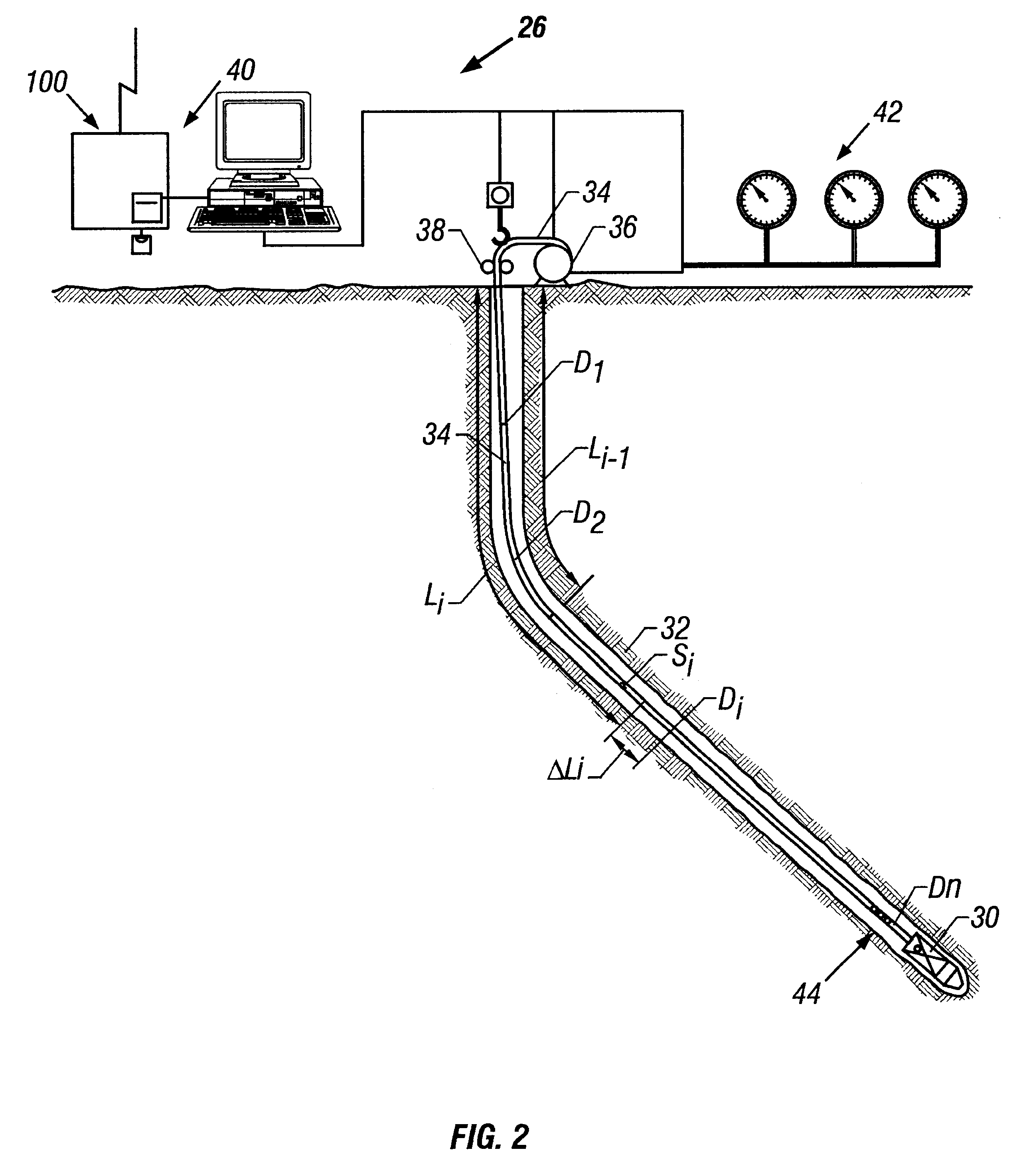
The present invention features a system and method for determining a sub-surface length of tubulars made of materials that deform when exposed to environmental factors. The sub-surface length of the tubing generally represents the measured depth. For a well having a composite coiled tubing umbilical extending from the surface to a bottom hole assembly in a well bore, an embodiment of a preferred system includes a surface processor, surface sensors, downhole sensors and a telemetry system. The surface processor includes software that determines an environ-mental profile for the tubing using the environmental data retrieved by the downhole and surface sensors. By applying the environmental profile to the surface-measured length of the tubing umbilical, the computer software calculates the sub-surface length of the tubing umbilical.

An embodiment of the software includes a memory module, a monitoring module, and a calculating module. Calculated values, as well as data relating to tubing...


PUM


Abstract

A surface processor uses an environmental profile to determine the sub-surface length of tubing disposed in a well bore. Information relating to tubing properties is stored in a memory module of the surface processor. The environmental profile includes data relating to well bore ambient conditions and the operating parameters of well equipment. Surface processor calculates the tubing elongation or length reduction corresponding to the environmental profile. Surface processor may repeat this process to develop a measured depth chart for a well. Logging operations performed in conjunction with the sub-surface length calculations allows formation data to be associated with the measured depth chart.

Description

Not Applicable.1. Field of the InventionThe present invention relates to a system for determining the drilled distance between the surface and a point in a well bore. More particularly, the present invention relates to a system using a processor that calculates true measured depth based on data received from surface sensors, downhole sensors, and in another aspect, the present invention relates to a method for using a tubular umbilical to determine the drilled distance between the surface and a point in a well bore. More particularly, the present invention provides a method for correcting a surface-measured length of a tubular umbilical to determine the sub-surface length of the tubular umbilical by using an environmental profile to calculate length corrections. Still more particularly, the present invention relates to methods using temperature differentials, pressure differentials and axial loadings to correct a surface-measured length of a composite coiled tubing umbilical to dete...

Claims


Application Information

Patent Timeline
IPC IPC(8): E21B47/022E21B47/02E21B47/04G01B5/00G01B21/02
CPCE21B47/022E21B47/04G01B5/0011
Inventor SONG, HAOSHIRIOS-ALEMAN, DAVID E.
Owner HALLIBURTON ENERGY SERVICES INC
Learn More