Air cleaner for removing air pollutants by water spray type of dust collecting system

a technology of air cleaner and dust collection system, which is applied in the direction of dispersed particle separation, separation process, chemical apparatus and processes, etc., can solve the problems of high maintenance cost, inability to completely remove air pollutants with extreme fine particles such as noxious gases, heavy metal gases, etc., and achieves the effect of reducing maintenance cost and high spray pressur

Inactive Publication Date: 2002-09-17
KOREAN CLEAN AIR SYST +2
View PDF19 Cites 51 Cited by
  • Summary
  • Abstract
  • Description
  • Claims
  • Application Information

AI Technical Summary

Benefits of technology

to provide an air cleaner for removing air pollutants by a water spray type of dust collecting system which is capable of separating a dust collecting part and an air and water separating part in the interior of a duct through which air is passed, wherein the dust collecting part is comprised of opposing water spray type primary and secondary dust collectors by water spraying and a space dust collector by water spraying installed between the primary and secondary dust collectors by water spraying, such that the surface tension of the water by the three-step air and water contact causes the dust and gases in the air to be absorbed and dissolved, resulting in settling of the absorbed and dissolved dust and gases, thereby ma

Problems solved by technology

However, such type of air cleaners can remove foreign materials such as dust, but fail to completely remove air pollutants having extreme fine particles such as noxious gases, heavy metals gases and so on.
However, the colliding plates 104 cut the flowing path of air in the zigzag manner, resulting in the hindrance of the smooth air flowing due to a high resistance of air.
To solve this problem, therefore, the prior art

Method used


Image

  • Air cleaner for removing air pollutants by water spray type of dust collecting system
  • Air cleaner for removing air pollutants by water spray type of dust collecting system
  • Air cleaner for removing air pollutants by water spray type of dust collecting system

Examples


Embodiment Construction

Reference will now be made in detail to the preferred embodiments of the present invention, examples of which are illustrated in the accompanying drawings.

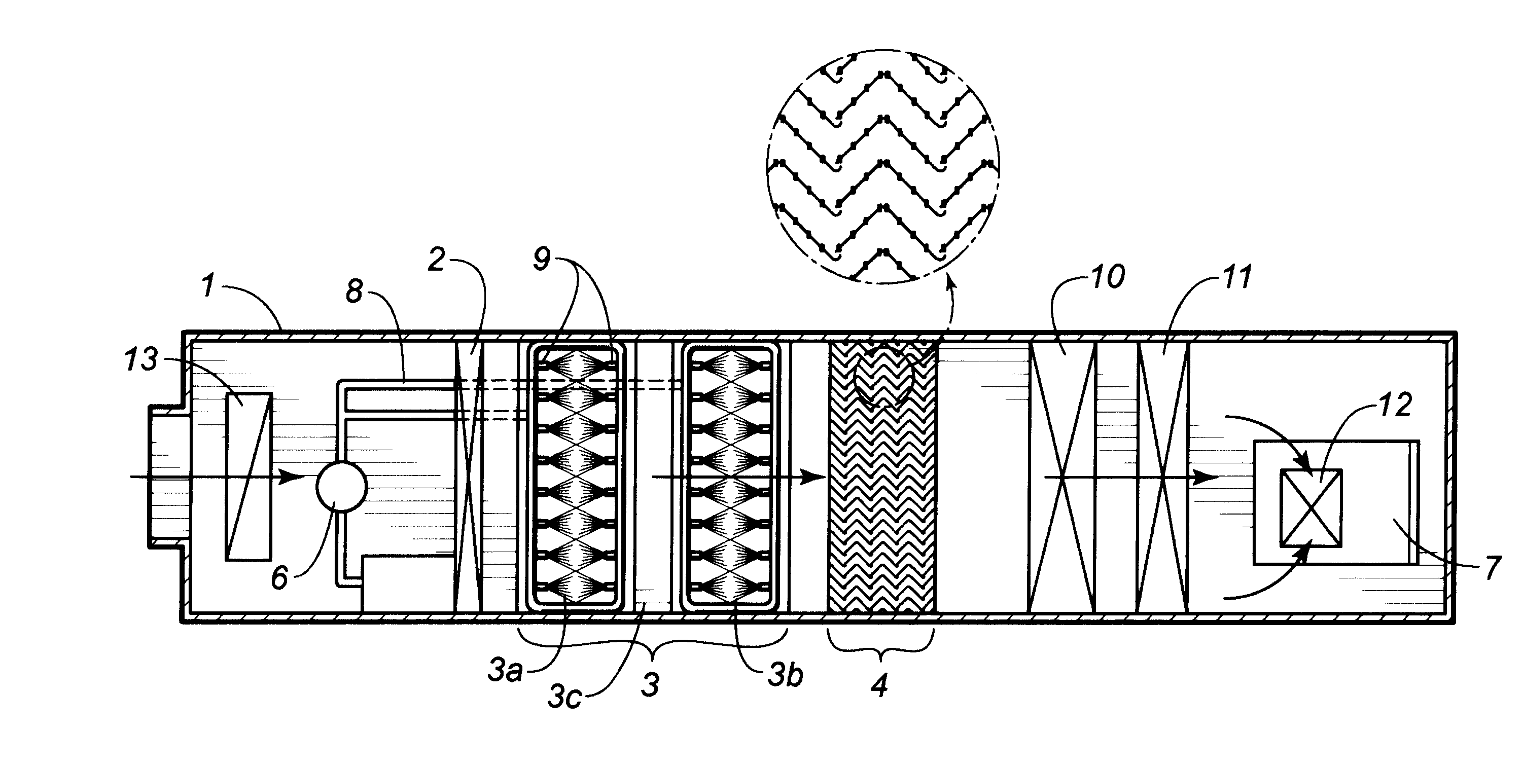
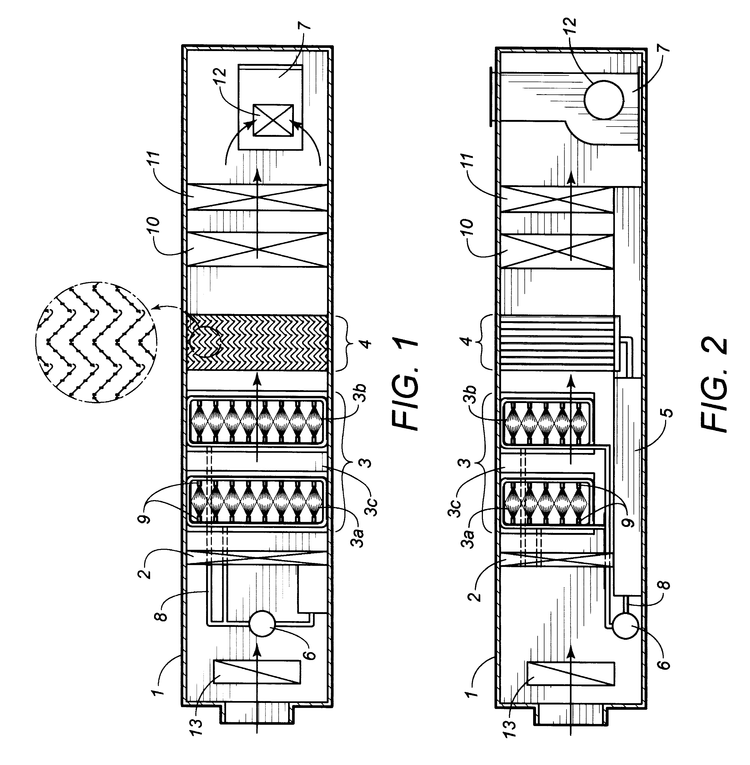
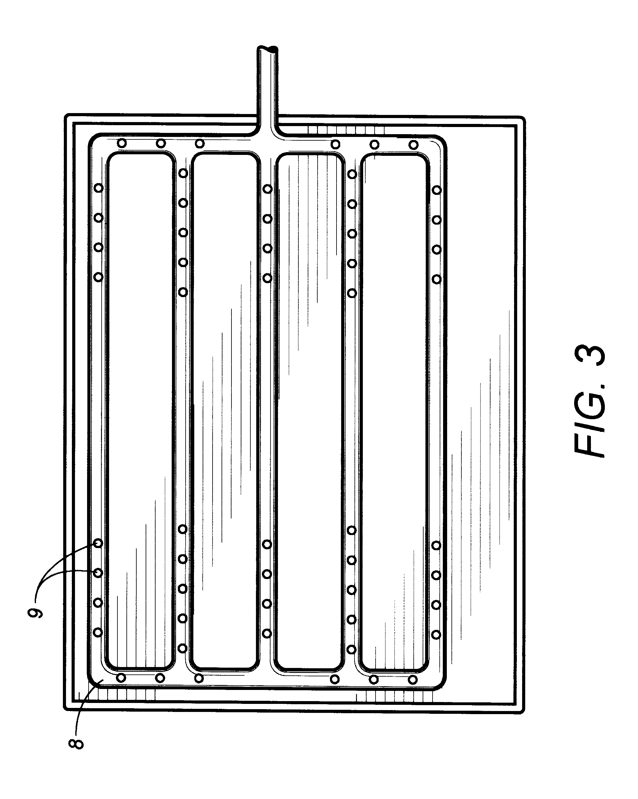
Now, an explanation of the construction of an air cleaner according to the present invention will be in detail discussed with reference to FIGS. 1 to 3.

In construction, the air cleaner according to the present invention has a basic construction in which a water blowing preventing louver 2, a dust collecting part 3, an air and water separating part 4, a water tank 5, a pump 6 and a blower 7 in the interior of a duct type of body 1. The dust collecting part 3 is comprised of an opposed water spraying type primary and secondary dust collectors by water sprayers 3a and 3b and a space dust collector 1496-3 formed in a space between the primary and secondary dust collectors by water sprayers 3a and 3b. Each of the dust collectors by water spraying is configured in a unit of a pipe 8 and a plurality of nozzles, and the pipe 8 is position...


PUM

PropertyMeasurementUnit
Angleaaaaaaaaaa
Angleaaaaaaaaaa
Pressureaaaaaaaaaa

Abstract

An air cleaner for removing air pollutants by a water spray type of dust collecting system, which includes a dust collecting part and an air and water separating part in the interior of an air duct, the dust collecting part composed of primary and secondary dust collectors by water spraying, each of which having a plurality of spraying nozzles layeredly arranged by predetermined intervals to be opposed at an angle of 30° from the top to bottom thereof, and a space dust collector by water spraying disposed in a space between the primary and secondary dust collectors by water spraying, such that the three-step air and water contact causes foreign materials such as dust, gases and so on to be absorbed, dissolved and settled, and the air and water separating part formed of a groove-engaged type and layeredly curved by six-step folding at an angle of 90° in consideration of air resistance, for passing only the air flowing from the dust collecting part and collecting water drops.

Description

1. Field of the InventionThe present invention relates to an air cleaner for removing air pollutants by a water spray type of dust collecting system, and more particularly, to an air cleaner for removing dust, gases and all kinds of noxious materials dispersed in the external air to supply a fresh air within a room.2. Discussion of Related ArtAs well known, there are developed a large number of air cleaners, most of which use a filter. However, such type of air cleaners can remove foreign materials such as dust, but fail to completely remove air pollutants having extreme fine particles such as noxious gases, heavy metals gases and so on. Therefore, an advanced type of air cleaner employs a plasma generator for burning the air pollutants or an electron beam generatorIn addition, there are several kinds of air cleaners for removing noxious gases by the application of a water spray method. A most recently developed method is disclosed in Japanese Patent Laid-open No. 2000-42338 (Feb. 1...

Claims


Application Information

Patent Timeline
IPC IPC(8): B01D53/75B01D53/74B01D50/00
CPCB01D47/12B01D50/008B01D53/75B01D50/10
Inventor KIM, JONG SOO
Owner KOREAN CLEAN AIR SYST
Why Eureka
Try Eureka