Methods for controlling deployment of an occupant restraint in a vehicle and determining whether the occupant is a child seat

a technology for determining whether an occupant is a child seat and a vehicle, which is applied in the direction of pedestrian/occupant safety arrangement, using reradiation, instruments, etc., can solve the problems of serious injury or death of children in rear facing child seats placed on the right front passenger seats, vehicle occupants, and inability to detect children, etc., to achieve highly reliable occupant presence and position system, high reliability of object classification

Inactive Publication Date: 2002-09-17
AMERICAN VEHICULAR SCI
View PDF41 Cites 76 Cited by
  • Summary
  • Abstract
  • Description
  • Claims
  • Application Information

AI Technical Summary

Benefits of technology

1. To provide a reliable method for developing and adapting a system for recognizing the presence of a rear-facing child seat on a particular seat of a motor vehicle.
2. To provide a reliable method for developing and adapting a system for recognizing the presence of a human being on a particular seat of a motor vehicle.
3. To provide a reliable method for developing and adapting a system for determining the position, velocity or size of an occupant in a motor vehicle.
4. To provide a reliable method for developing and adapting a system for determining in a timely manner that an occupant is out-of-position, or will become out-of-position, and likely to be injured by a deploying airbag.
5. To provide a method for locating transducers within the passenger compartment at specific locations such that a high reliability of classification of objects and their position is obtained from the signals generated by the transducers.
6. To provide a method for combining a variety of transducers including seatbelt payout sensors, seatbelt buckle sensors, seat position sensors, seatback position sensors, and weight sensors into a system and adapt that system so as to provide a highly reliable occupant presence and position system when used in combination with electromagnetic, ultrasonic or other radiation sensors.

Problems solved by technology

Whereas thousands of lives have been saved by airbags, a large number of people have also been injured, some seriously, by the deploying airbag, and thus significant improvements to the airbag system are necessary.
As discussed in detail in one or more of the patents and patent applications cross-referenced above, for a variety of reasons, vehicle occupants may be too close to the airbag before it deploys and can be seriously injured or killed as a result of any deployment thereof.
Also, a child in a rear facing child seat which is placed on the right front passenger seat is in danger of being seriously injured if the passenger airbag deploys.
In addition to eliminating the disturbance and possible harm of unnecessary airbag deployments, the cost of replacing these airbags will be excessive if they all deploy in an accident needlessly.
However, no patents have been found that describe the methods of adapting such sensors to a particular vehicle model to obtain high system accuracy.
Each of these systems will be discussed below and have significant limitations.
White et al. does not disclose where the such sensors would be mounted, other than on the instrument panel below the steering wheel, or how they would be combined to uniquely monitor particular locations in the passenger compartment and to identify the object(s) occupying those locations.
Both such mounting locations are particularly prone to detection errors due to positioning of the occupant's hands, arms and legs.
Such a combination, however, would not differentiate between an occupant with both hands and arms in the path of the ultrasonic transmitter at such a location that they were blocking a substantial view of the occupant's head or chest.
In fact, the closer that the occupant gets to the airbag, the faster the inflation rate of the airbag is according to the Fujita et al. patent, which thereby increases the possibility of injuring the occupant.
"Out-of-position" as used for an occupant will generally means that the occupant, either the driver or a passenger, is sufficiently close to the occupant protection apparatus (airbag) prior to deployment that he or she is likely to be more seriously injured by the deployment event itself than by the accident.
It may also mean that the occupant is not positioned appropriately in order to attain beneficial, restraining effects of the deployment of the airbag.
Such a system can be defeated if the driver is wearing glasses, particularly sunglasses, or another optical device which obstructs a clear view of his / her eyes.
Rather, Ando is limited to control of vehicle devices by responding to motion of the driver's mouth and eyes.
Also, Faris does not use trainable pattern recognition techniques such as neural networks.
Similarly, the implementation of the techniques of the above-referenced patents requires expensive microprocessors while the implementation with neural networks and similar trainable pattern recognition technologies permits the use of low cost microprocessors typically costing less than about $5 in quantities of one million per year.
First, the speed of sound limits the rate at which the position of the occupant can be updated to approximately 10 milliseconds, which though sufficient for most cases, is marginal if the position of the occupant is to be tracked during a vehicle crash.
Second, ultrasound waves are diffracted by changes in air density that can occur when the heater or air conditioner is operated or when there is a high-speed flow of air past the transducer.
Third, the resolution of ultrasound is limited by its wavelength and by the transducers, which are high Q tuned devices.
Finally, the fields from ultrasonic transducers are difficult to control so that reflections from unwanted objects or surfaces add noise to the data.

Method used


Image

  • Methods for controlling deployment of an occupant restraint in a vehicle and determining whether the occupant is a child seat
  • Methods for controlling deployment of an occupant restraint in a vehicle and determining whether the occupant is a child seat
  • Methods for controlling deployment of an occupant restraint in a vehicle and determining whether the occupant is a child seat

Examples


Embodiment Construction

. Introduction

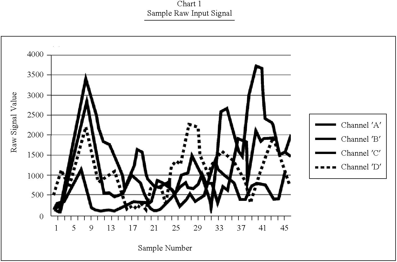
The Artificial Neural Network that forms the "brains" of the Occupant Spatial Sensor needs to be trained to recognize airbag enable and disable patterns. The most important part of this training is the data that is collected in the vehicle, which provides the patterns corresponding to these respective configurations. Manipulation of this data (such as filtering) is appropriate if this enhances the information contained in the data. Important too, are the basic network architecture and training methods applied, as these two determine the learning and generalization capabilities of the neural network. The ultimate test for all methods and filters is their effect on the network performance against real world situations.

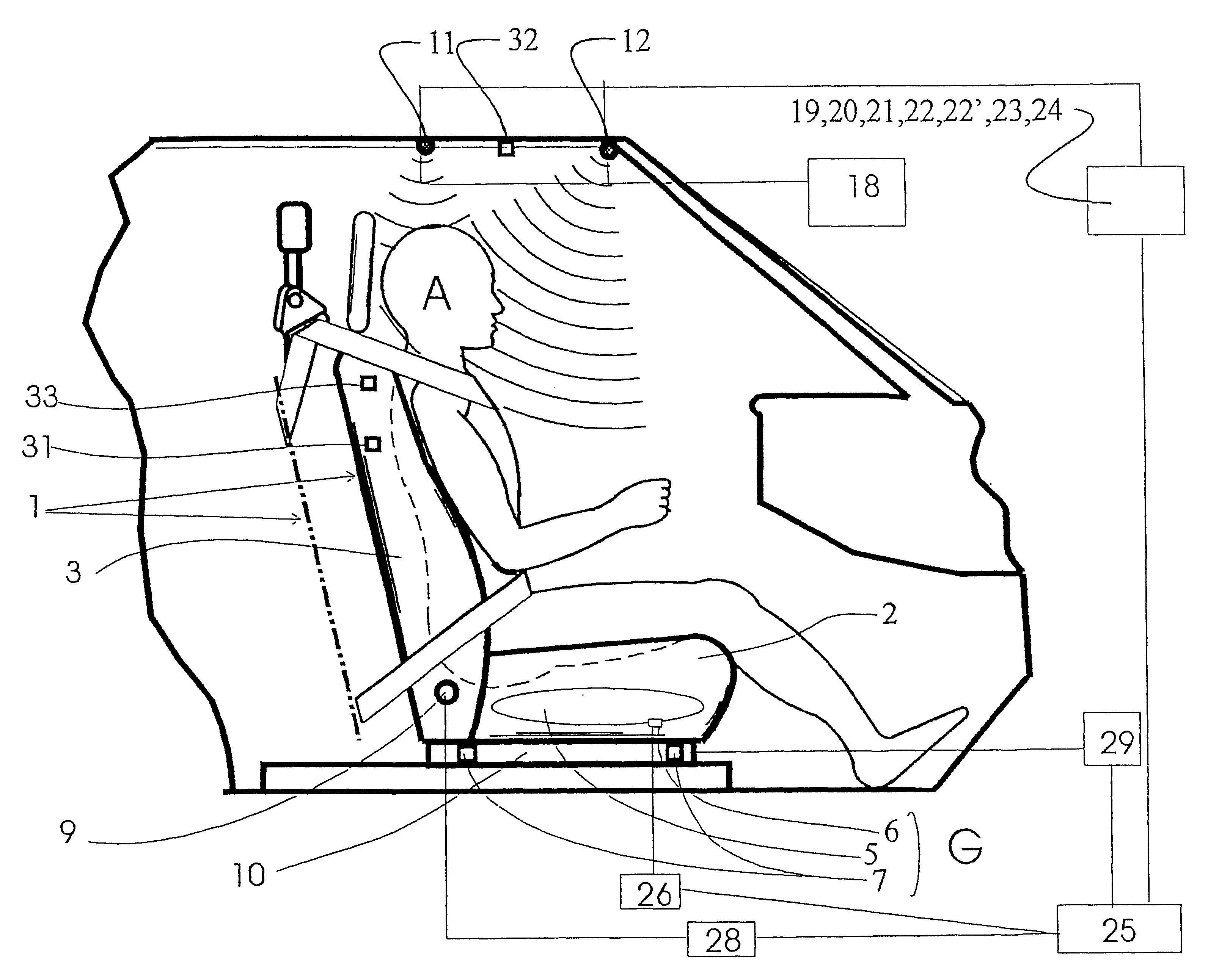
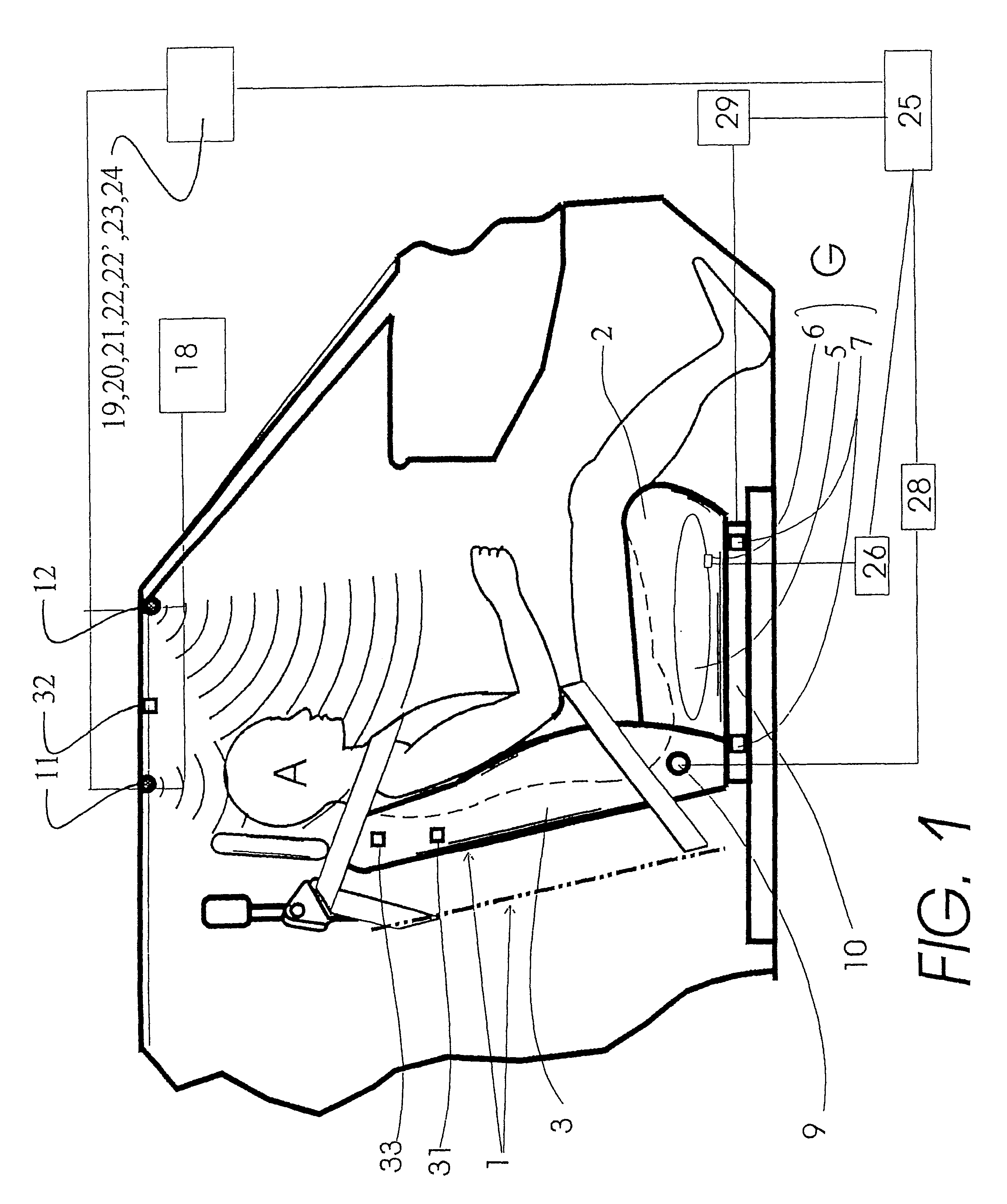
The Occupant Spatial Sensor (OSS) uses an artificial neural network (ANN) to recognize patterns that it has been trained to identify as either airbag enable or airbag disable conditions. The pattern is obtained from four ultrasonic transducers that cover th...


PUM


Abstract

Methods for controlling deployment of an occupant restraint device in a vehicle and determining whether an object is a child seat in which one ultrasonic transducer is arranged on a ceiling of the vehicle and another ultrasonic transducer is arranged at a different location in the vehicle, ultrasonic waves are transmitted from each transducer into the passenger compartment and received thereby, and the distance from each transducer to the object is calculated based on the time difference between the transmitted waves when transmitted from the transducer and the reflected waves when received at the transducer. Deployment of the occupant restraint device is controlled based on the calculated distances and/or a determination is made whether the object is a child seat based on the calculated distances.

Description

This application claims priority under 35 U.S.C. .sctn.119(e) of U.S. provisional patent application Ser. No. 60 / 136,163 filed May 27, 1999 through the parent applications.This application is related to: (i) U.S. Pat. No. 5,653,462 entitled "Vehicle Occupant Position and Velocity Sensor" filed Jul. 21, 1995, which is a continuation of U.S. patent application Ser. No. 08 / 040,978 filed Mar. 31, 1993, now abandoned, which in turn is a continuation of U.S. patent application Ser. No. 07 / 878,571 filed May 5, 1992, now abandoned; (ii) U.S. Pat. No. 5,829,782 entitled "Vehicle Interior Identification and Monitoring System" filed May 9, 1994; (iii) U.S. Pat. No. 5,845,000 entitled "Optical Identification and Monitoring System Using Pattern Recognition for Use with Vehicles" filed Jun. 7, 1995; (iv) U.S. Pat. No. 5,822,707 entitled "Automatic Vehicle Seat Adjuster" filed Jun. 7, 1995; (v) U.S. Pat. No. 5,748,473 entitled "Automatic Vehicle Seat Adjuster" filed Jun. 7, 1995; and, (vi) U.S. Pa...

Claims


Application Information

Patent Timeline
Patent Type & Authority Patents(United States)
IPC IPC(8): B60R21/01G01S15/04G01S15/42G01S15/00G06K9/00G01S15/88B60R21/015
CPCG01S15/04G01S15/42G06K9/00362B60R21/01554B60R21/01546B60R21/01536B60R21/01532B60R21/01516B60R21/01534B60R21/0152G01S15/88B60R21/01548G06V40/10
Inventor BREED, DAVID S.DUVALL, WILBUR E.VARGA, ANDREW J.
Owner AMERICAN VEHICULAR SCI
Why Eureka
Try Eureka