Exhaust gas measuring instrument

a technology of exhaust gas and measuring instruments, applied in instruments, liquid/fluent solid measurement, volume/mass flow by differential pressure, etc., can solve the problems that conventional exhaust gas measuring instruments using a mini-dilution tunnel cannot perform exhaust gas component measurement in the transient operation mode, and conventional exhaust gas measuring instruments using a mini-dilution tunnel can not achieve the effect of transient operation mod

Inactive Publication Date: 2002-10-08
HINO MOTORS LTD
View PDF8 Cites 25 Cited by
  • Summary
  • Abstract
  • Description
  • Claims
  • Application Information

AI Technical Summary

Benefits of technology

An object of the present invention is to eliminate the disadvantages of the conventional exhaust gas measuring instrument and to provide a fast-response exhaust gas measuring instrument using a mini-dilution tunnel and capable of measuring the amount of various components in exhaust gas in the transient operation mode of an engine. A particular object of the present invention is to provide an exhaust gas measuring instrument in which a bypassed gas flow meter f

Problems solved by technology

Because a long time is needed for the concentration to reach a stable state, the conventional exhaust gas measuring instrument cannot be used in the transient operation mode.
In other words, the conventional exhaust gas measuring instrument using a mini-dilution

Method used


Image

  • Exhaust gas measuring instrument
  • Exhaust gas measuring instrument
  • Exhaust gas measuring instrument

Examples


Embodiment Construction

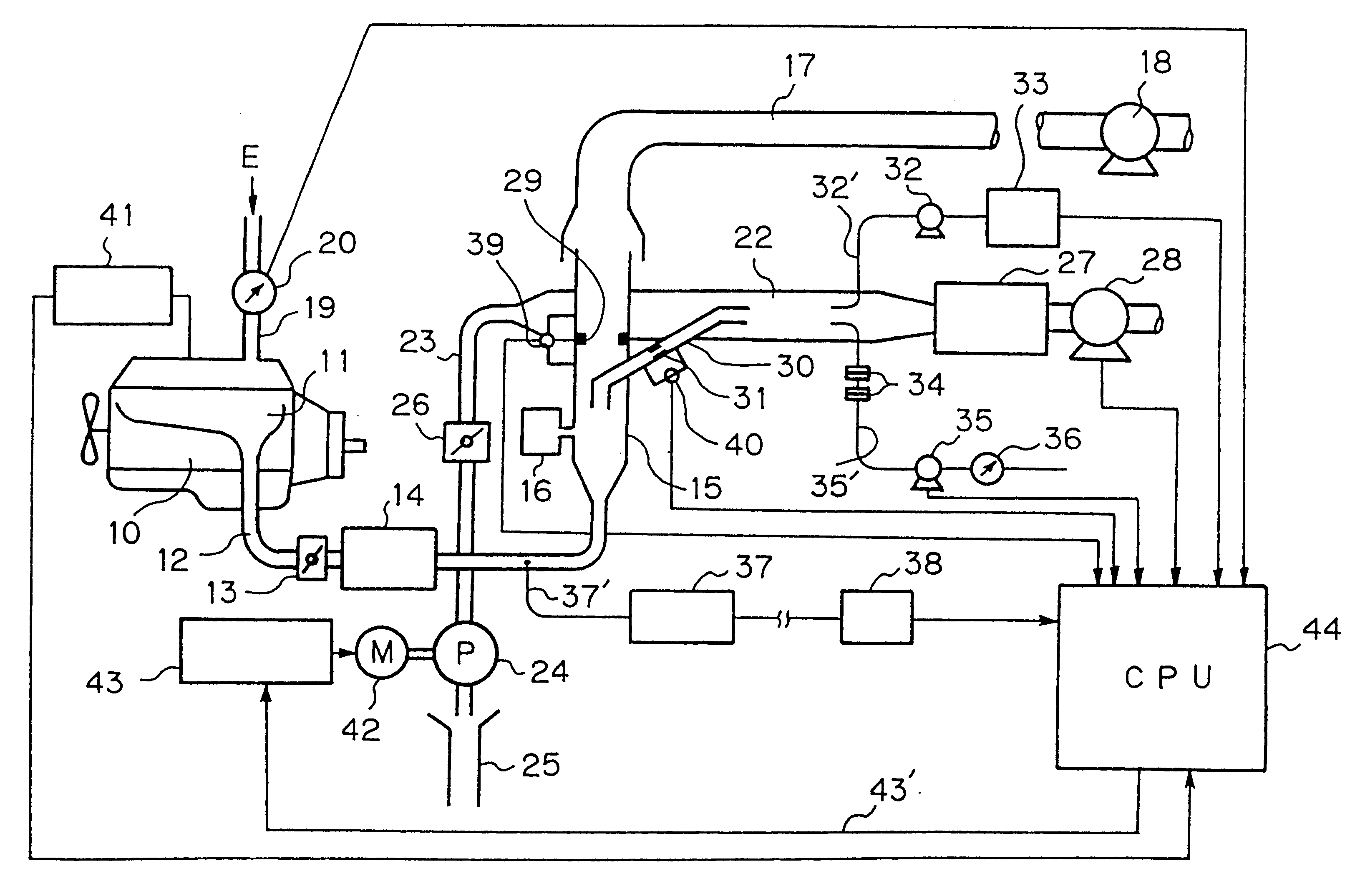
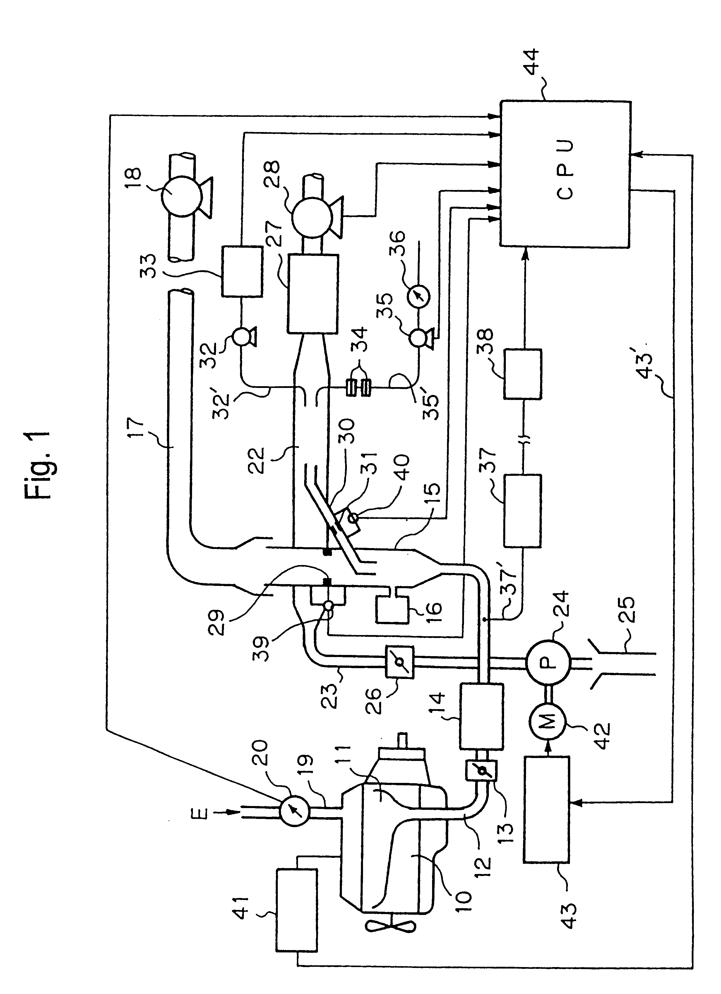
A plurality of embodiments of the present invention will be described below with reference to the drawings. However, the technical scope of the present invention is not limited to these embodiments but defined by the scope of the appended claims. FIG. 1 is a layout plan showing the whole arrangement of an exhaust gas measuring instrument according to one embodiment of the present invention. An exhaust pipe 12 is connected to an exhaust manifold 11 attached to a side of a diesel engine 10. A butterfly valve 13 for exhaust pressure regulation and a muffler 14 are connected to the exhaust pipe 12.

The outlet side of the muffler 14 is connected to another exhaust pipe 15. A resonator 16 for preventing pulsation is connected to the exhaust pipe 15 in such a manner as to branch out from it. The upper end of the exhaust pipe 15 is open to the atmosphere. The portion of the exhaust pipe 15 that is open to the atmosphere extends into the inlet portion of a flue 17. An exhaust blower 18 is con...


PUM


Abstract

An exhaust gas measuring instrument has a mini-dilution tunnel (22) in which a part of exhaust in the exhaust pipe (15) of an engine is introduced through sampling tube (30) and diluted with air. The exhaust gas is diluted in the mini-dilution tunnel (22), a high response differential pressure type extracted gas flow meter (31 and 40) measures the exhaust gas flow rate (Qs) in the sampling tube (30). A high response differential pressure type bypassed gas flow meter (29 and 39) measures the exhaust gas flow rate (Qb) in the exhaust pipe (15). The flow rate split ratio R=Qb/Qs is obtained by dividing the exhaust gas flow rate (Qb) by the exhaust gas flow rate (Qs). A calibration coefficient (k) of the flow rate split ratio is obtained and the calibrated flow rate split ratio (k.R) is calculated by multiplying the flow rate split ration by the calibration coefficient.

Description

The present invention relates to an exhaust gas measuring instrument using a mini-dilution tunnel to measure the amount of emission of various components in exhaust gas from an engine. The mini-dilution tunnel is arranged such that a part of exhaust gas is extracted from an exhaust pipe of the engine and introduced into the mini-dilution tunnel through a sampling tube and then diluted with air to lower the exhaust gas temperature.A mini-dilution tunnel is used to measure the amount of emission of various components in exhaust gas from engines, particularly diesel engines. The mini-dilution tunnel lowers the temperature of extracted exhaust gas to 52.degree. C., for example, thereby creating a condition in which various components in the exhaust gas condense into particulate matter as a result of the lowering in temperature. An exhaust gas measuring instrument using a mini-dilution tunnel measures the concentration of exhaust gas components such as nitrogen oxides in a state approxim...

Claims


Application Information

Patent Timeline
IPC IPC(8): G01F1/34G01F1/38G01N1/22G01F1/36G01F5/00G01N33/00G01F1/00G01F1/42
CPCG01F1/363G01F1/383G01F5/00G01N1/2252G01N33/0018G01N33/0006G01N2001/2264G01N1/22
Inventor ICHIKAWA, JUN
Owner HINO MOTORS LTD
Why Eureka
Try Eureka