The BHM approach has many recognized advantages, but the method has not gained acceptance commensurate with its potential due to several important issues that have yet to be finalized.
One of the most significant problems has been the specialized tooling needed for mining of different type of material and specific geo-technical and environmental tasks to be performed, which requires that the
user needs to carry and the use of different tools to the
work site instead of a universal one.
These tools are typically large and heavy units having a minimum number of joints, couplings, threads and other easy-and-quick connectors which complicates the tool's
assembly,
accessibility, serviceability and replacement.
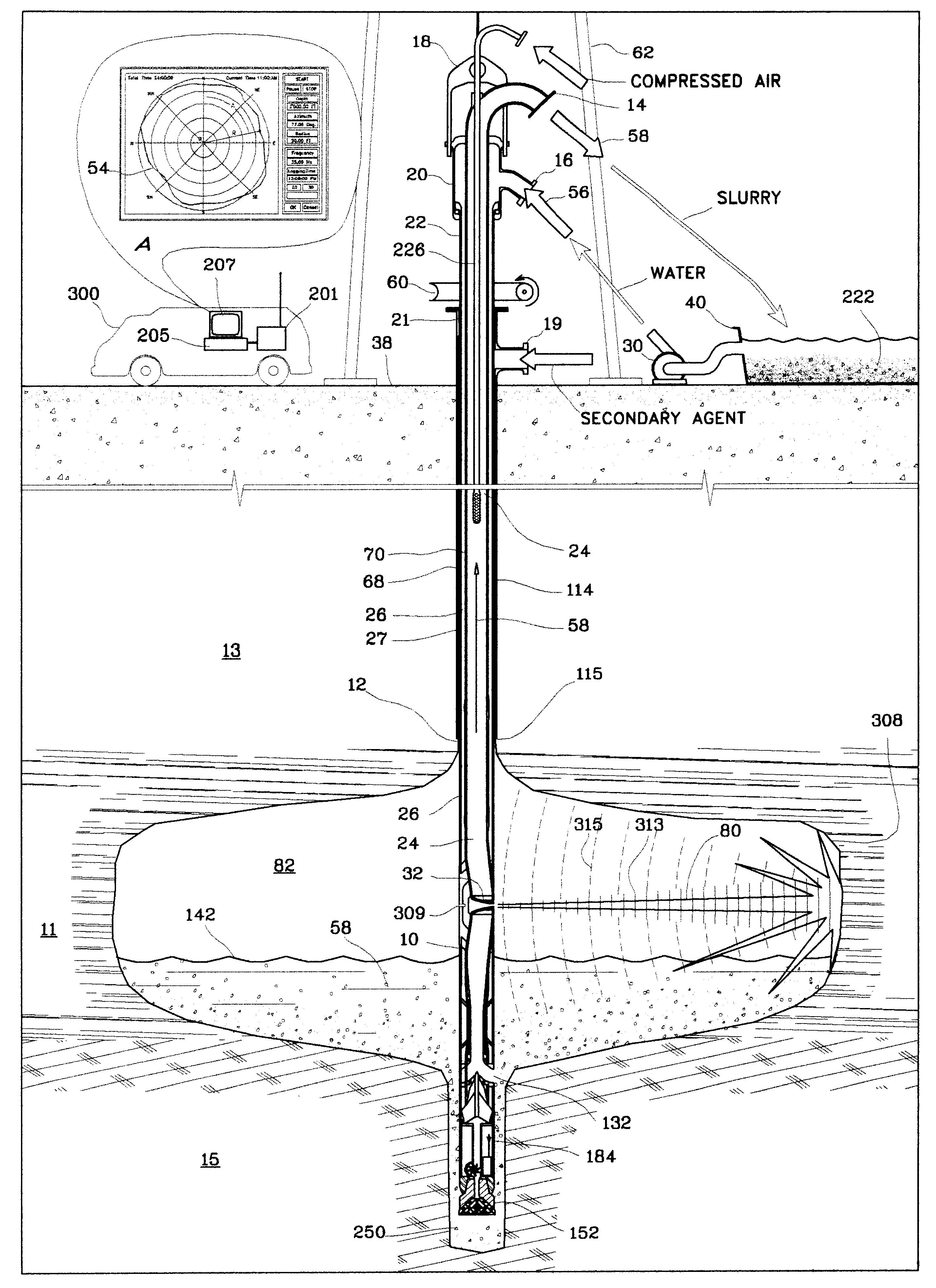
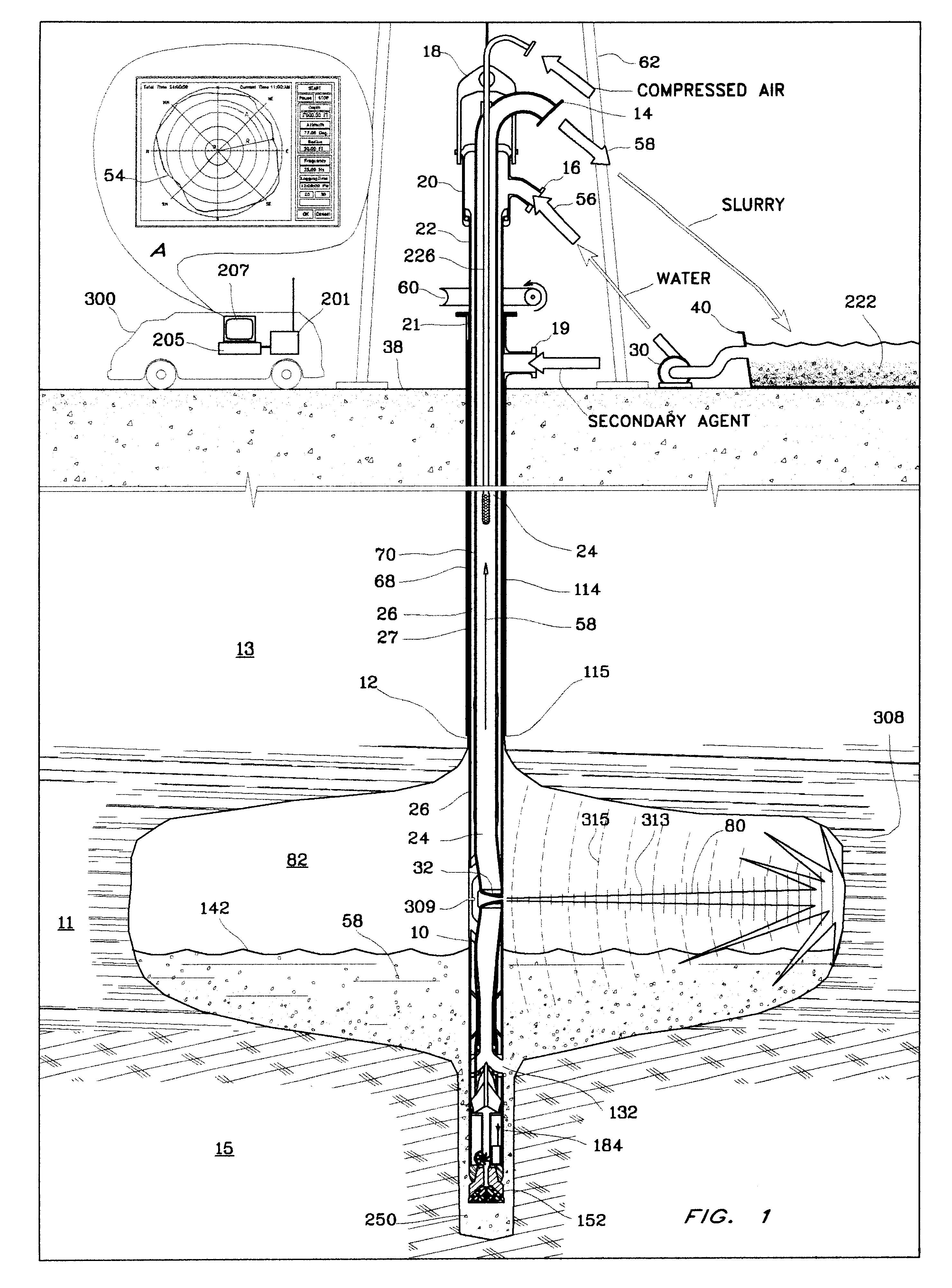
Another problem is that borehole mining is a blind method; there is no data about the current
cutting direction as well as the current configuration of the driving space (cavern / stopes).
Thus, measurements, made after stopping of operation can not always be used for
estimation of production.
In this task, information about orientation of the tool's
nozzle down in a borehole becomes very critical.
Thus, after the tool is assembled and lowered down in a hole, there is no further information about the current bottom head's
nozzle orientation; as it is lost while assembling.
The need for high reliability is a critical element for borehole mining tools, since failure of a component at a great depth can result in long down times and expensive procedures for trying to retrieve the tool through the borehole.
Often, however, the orifice used to draw material is not at the lowest point on the tool.
This is a serious
disadvantage since the solids of the
slurry will tend to settle and fill this low area.
Known devices for borehole mining have suffered from limited applicability.
This tool is not free from disadvantages.
The
drill bit located below the eductor does not allow slurry to be recovered from the very lowest points of the working area.
Thus, this tool can not be successfully used, for example in cleaning of oil (or any other) storage, vessel or tank.
The other
disadvantage of this invention is the usage of an external pipe as a slurry channel.
It excludes the possibility of using an
airlift because there is no simple method to place an air pipe in this gap due to its rotation.
Finally, these "double" walls increase the slurry pressure loss nearly two-fold due to the doubled hydraulic friction.
The above mentioned disadvantages narrow the area of this tool application.
U.S. Pat. No. 5,366,030 to
Pool has a design similar to Paveliev construction and is suffering from the same problems.
Additionally, both devices have only two hydraulic channels.
1. Limited area of application. The tool can not remove the slurry at the lowest point of the working area because below the suction area is located the distribution reservoir and the
drill bit.
2. A high number of moving mechanisms, parts, springs, pistons and cylinders decrease the reliability of the device, while increasing hydraulic friction and
water pressure loss.
3. The inlet to the hydromonitor is located very close to the outer pipe wall. Part of the
high pressure water flow makes a sharp turn to come into the hydromonitor at this point. The very
high velocity of the
water flow (5-10 m / sec), along with the sharp turn and the narrow space where this turn occurs, creates a high grade turbulence in
water flow right before the hydromonitor nozzle. As a result, it negatively reflects on the hydrodynamic characteristics of the
water jet: it becomes an unfocused, spray-type flow. Obviously, it therefore, decreases the water-jet productivity and also decreases the tool's overall borehole mining effectiveness.
The main
disadvantage of all the afore mentioned devices is their limited area of application.
Thus, for example, a tool which can effectively develop a sand-type material may not be very successful at the mining a clay-type material.
Another example: a device for borehole mining can not be effectively applied for the purpose of cleaning a
metal reservoir, and for creating underground pillars.
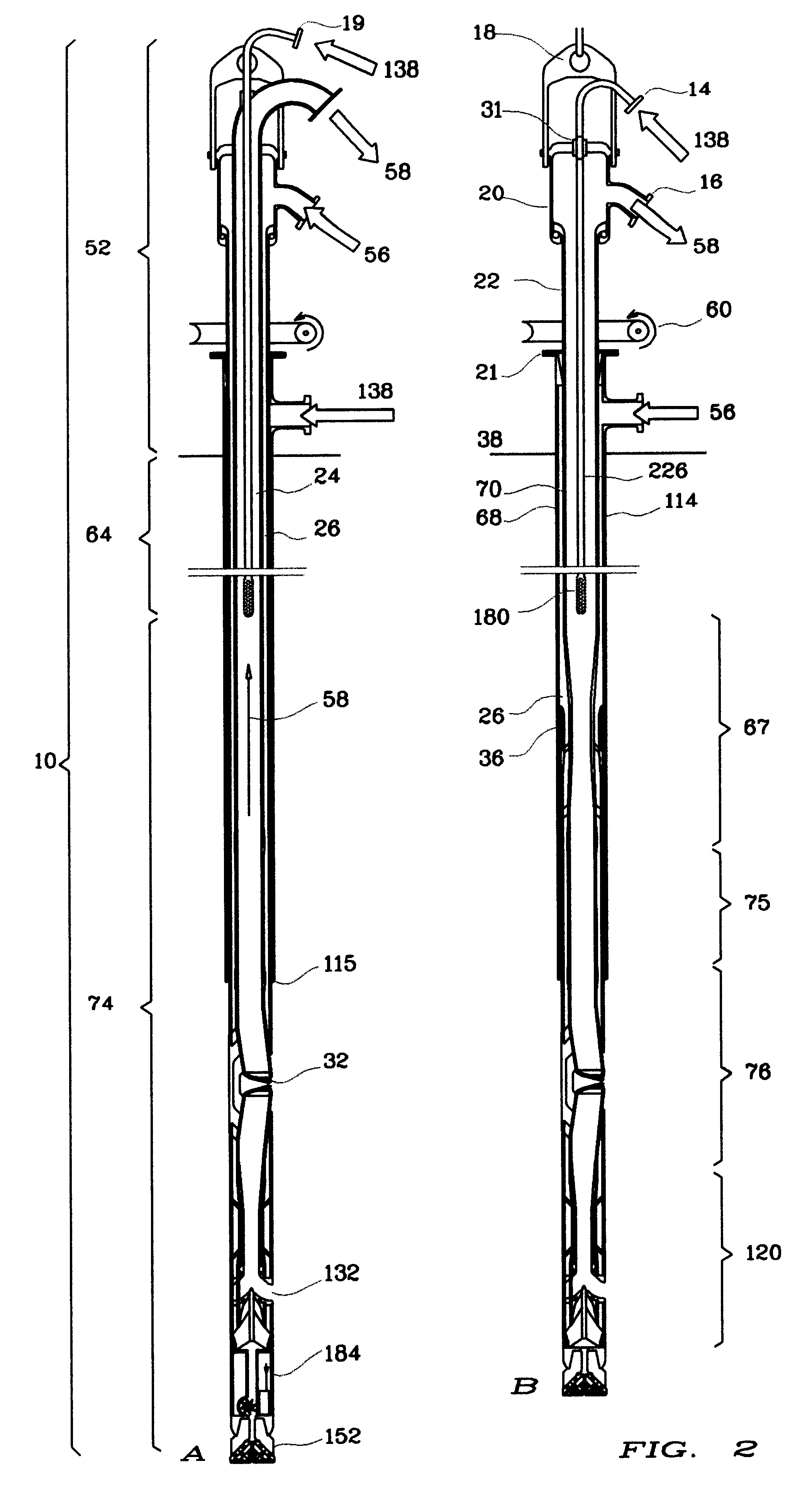
As it was shown before, in general, BHM tools have doubled body ("pipe-in-pipe") construction, which doubles the weight of the tool and limits the working depth because of the risk of the tool rupture and loss.
It also increases the tool initial and operational cost.
possibility of decreasing the weight of the device,

