Reduced-transistor, double-edged-triggered, static flip flop

a flip-flop, double-edged trigger technology, applied in the field of static flip-flops, can solve the problems of inefficient data flow, set flip-flop operating power cost, slow data flow,

Inactive Publication Date: 2002-10-08
IBM CORP
View PDF4 Cites 34 Cited by
  • Summary
  • Abstract
  • Description
  • Claims
  • Application Information

AI Technical Summary

Problems solved by technology

From a functional standpoint, they tend to be inefficient.
For example, because latching occurs on only one of the rising and falling edges of a clock signal, data flow tends to be slow, i.e., at only one half the clock edge frequency.
Also, because of their single clock-edge operation, SET flip-flops incur the power cost of operating at two clock edges per interval while using only one of the edges.
In a dynamic DET flip-flop, latched data is lost if the clock is slowed down below a certain level.
While

Method used


Image

  • Reduced-transistor, double-edged-triggered, static flip flop
  • Reduced-transistor, double-edged-triggered, static flip flop
  • Reduced-transistor, double-edged-triggered, static flip flop

Examples


Embodiment Construction

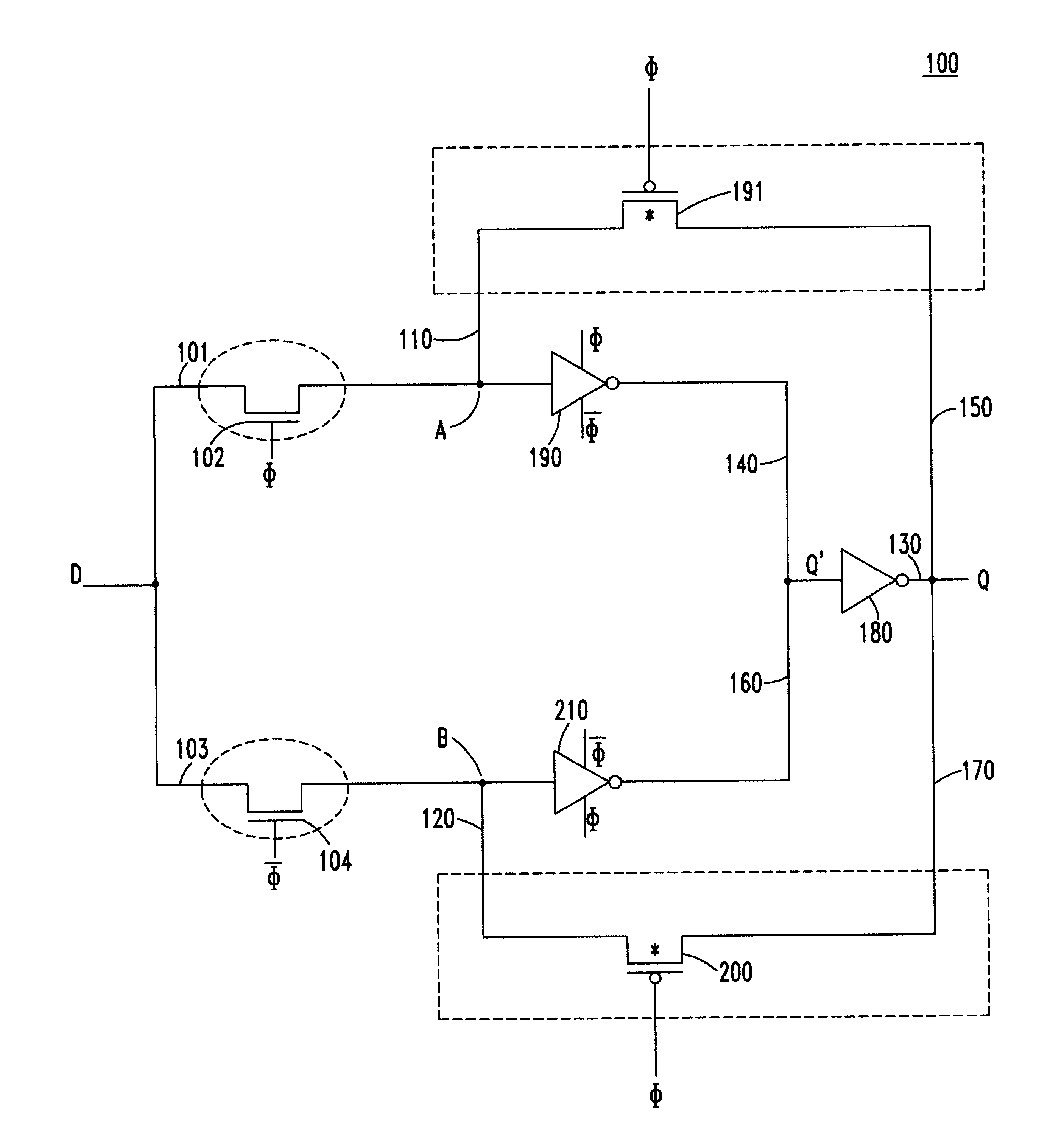
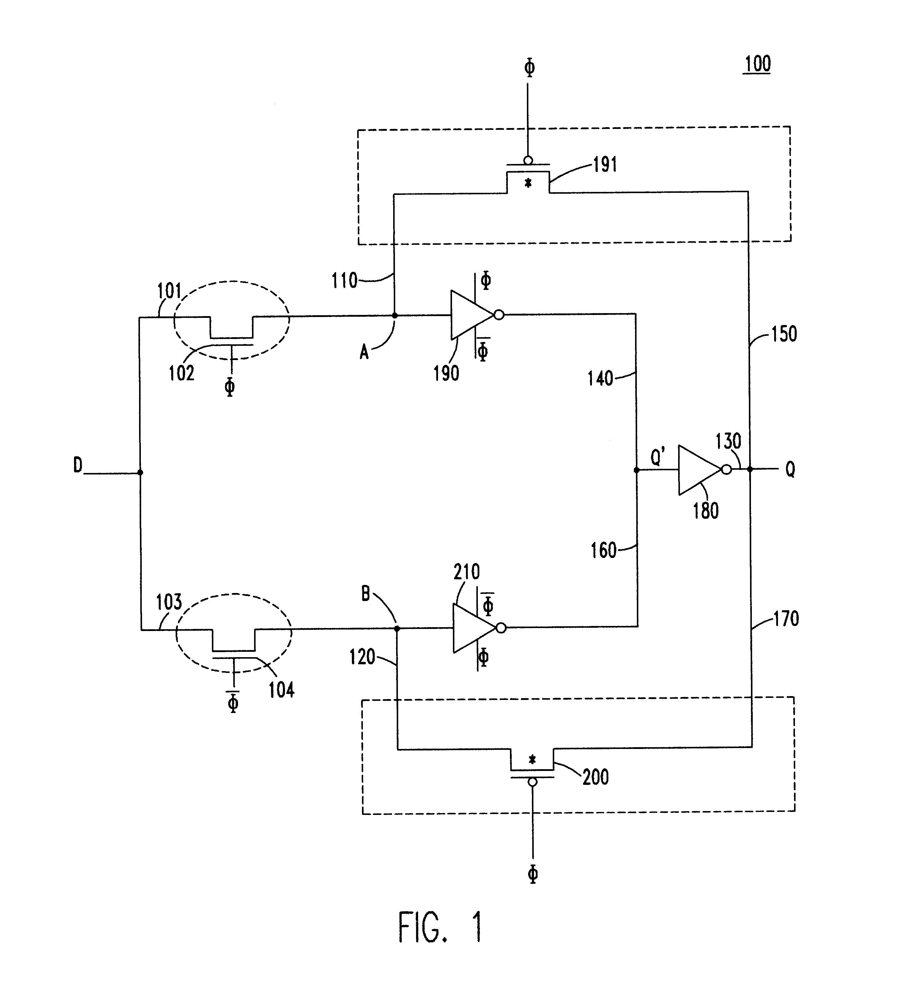
Referring to FIG. 1, a first embodiment of a static, double-edge-triggered flip-flop 100 in accordance with the present invention includes an upper data path and a lower data path connected between a data input node D and an output terminal Q. The upper data path 101 includes a pass transistor 102 connected to a first data loop 110, and the lower data path 103 includes a pass transistor 104 connected to a second data loop 120.

The first and second data loops are each formed from three paths. The first path is a forward path 130 which is shared by both loops and extends between node Q' and node Q. Shared path 130 includes an inverter 180 for performing a data inversion function. As will be explained in greater detail, the upper and lower paths are constructed to operate in accordance with different clock signals, which preferably are non-inverted and inverted clock signals .phi. and .phi.. When these signals are derived from the same clock, the flip-flop of present invention advantage...


PUM


Abstract

A static, double-edge-triggered flip-flop has an upper data path and a lower data path connected between a data input node and an output terminal. The upper path includes a switch connected to a first data loop, and the lower path includes a switch connected to a second data loop. The first and second data loops share a forward path having a data-inverting circuit. In addition, each loop has a feedback path which contains only one element in the form of a switch. However, no data-inverting circuit is included in either of the feedback paths. Advantageously, all the elements of the flip-flop may be constructed using MOSFET transistors implemented according to any one of a variety of semiconductor technologies. In more than one particularly advantageous embodiments, the flip-flop is constructed using a total of twelve transistors. Through this simplified two-loop design, operational efficiency is improved, low metastability is achieved and costs of manufacture are lowered, all while maintaining low power requirements.

Description

1. Field of the InventionThe present invention generally relates to logic circuits, and more particularly to static flip-flops which trigger on both the rising and falling edges of a clock signal.2. Background DescriptionIn order to reduce the complexity of circuit design, a large proportion of digital circuits are synchronous circuits; that is, they operate based on a clock signal. Among the more popular synchronous digital circuits are edge-triggered flip-flops. These flip-flops are desirable, especially in digital memories, registers, and caches, because they simplify circuit design, for example, by requiring stability of input data only during short intervals of time.Edge-triggered flip-flop circuits may be classified into one of two types. The first type latches data on either the rising edge or falling edge of a clock signal. While these so-called single-edge-triggered (SET) flip-flops are in common use today, they are not without drawbacks. From a functional standpoint, they ...

Claims


Application Information

Patent Timeline
IPC IPC(8): H03K3/00H03K3/356H03K3/012
CPCH03K3/356156H03K3/356173H03K3/012
Inventor VARMA, PRADEEP
Owner IBM CORP
Why Eureka
Try Eureka