Valve for controlling liquids

Inactive Publication Date: 2002-10-15
ROBERT BOSCH GMBH
View PDF11 Cites 12 Cited by
  • Summary
  • Abstract
  • Description
  • Claims
  • Application Information

AI Technical Summary

Problems solved by technology

Compensating for changes in length of the piezoelectric actuator, the valve member or the valve housing by means of the hydraulic chamber disposed between...

Method used


Image

  • Valve for controlling liquids
  • Valve for controlling liquids

Examples


Embodiment Construction

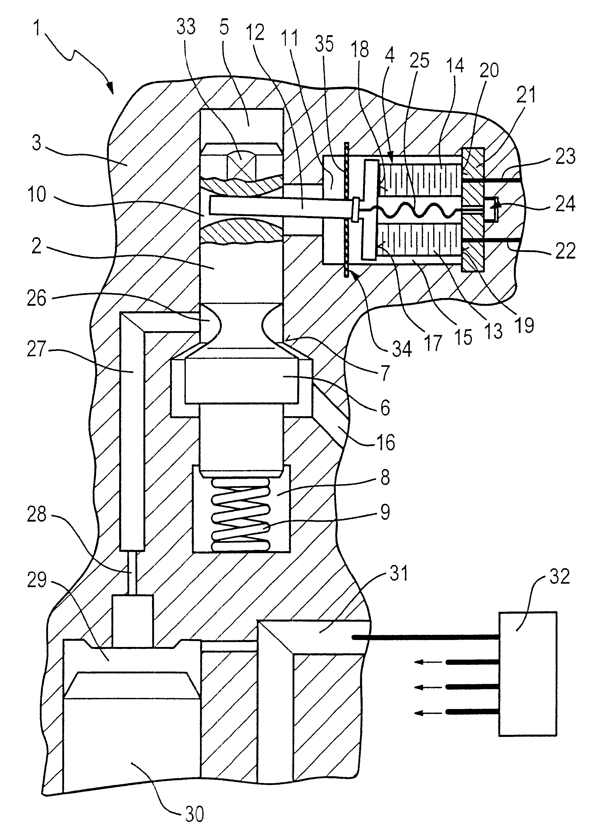
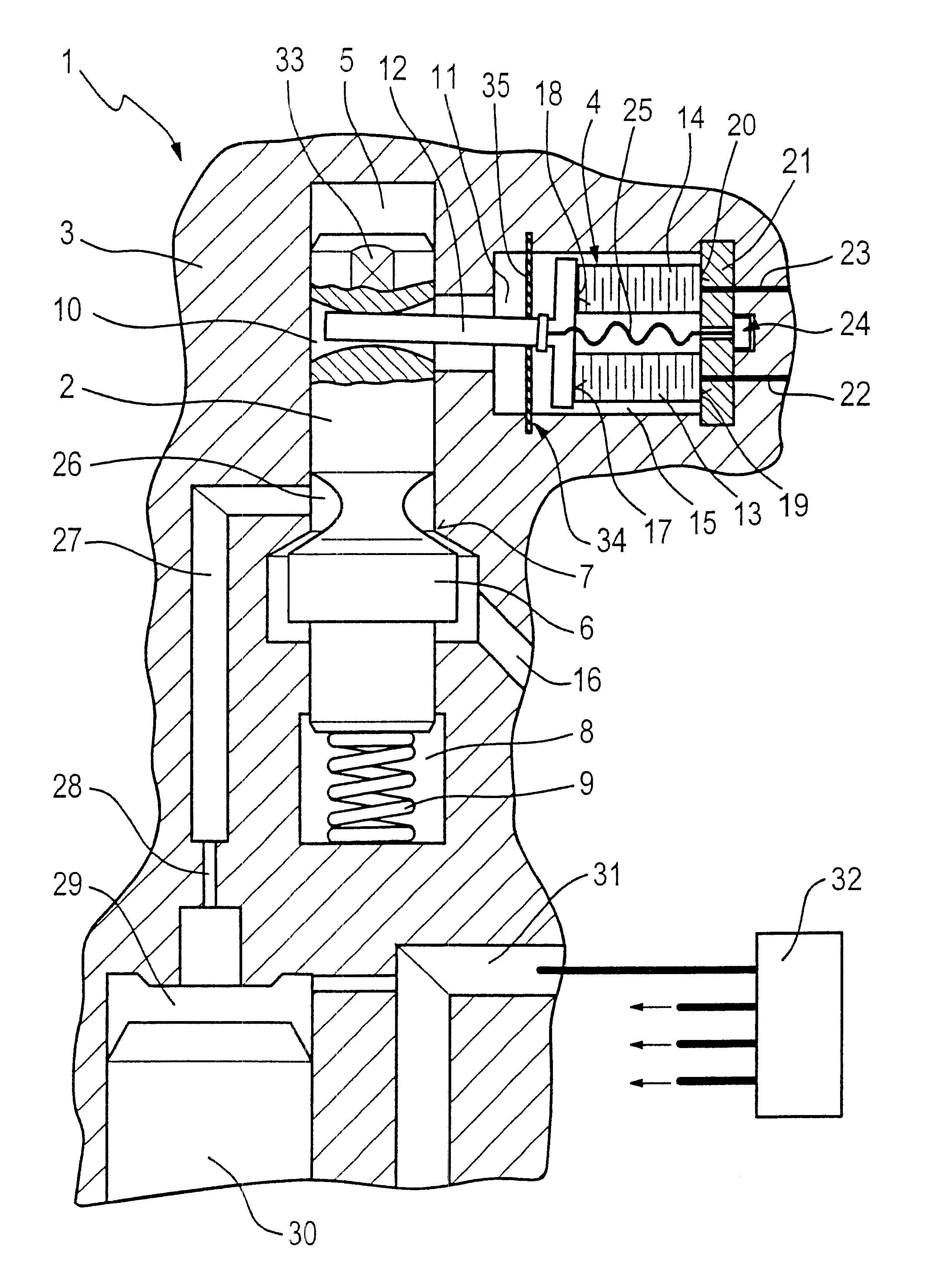
The exemplary embodiment shown in the drawing illustrates a use of the valve of the invention in a fuel injection valve 1 for internal combustion engines of motor vehicles. In the present case, the fuel injection valve 1 is embodied as a common rail injector.

To adjust an injection onset, duration of injection, and injection quantity by way of force ratios in the fuel injection valve 1, a valve member 2 disposed in a valve body 3 is triggered via a piezoelectric unit 4 with a piezoelectric actuator 4.

The pistonlike valve member 2 is disposed axially displaceably in a bore, embodied as a longitudinal bore 5, of the valve body 3, of the fuel injection valve 1, and on its lower end, toward the combustion chamber, it has a valve head 6 forming a valve closing member. The valve head 6 cooperates with a seat 7, embodied on the valve body 3, and in the raised state of the valve head 6, a communication is established with a spring chamber 8 having a spring 9 that exerts a restoring force on ...


PUM


Abstract

A valve (1) for controlling fluids is provided with a valve member (2), which is axially displaceable in a bore (5) of a valve body (3) and has a valve head (6), forming a valve closing member, that cooperates with a seat (7), provided on the valve body (3), for opening and closing the valve (1). A piezoelectric unit (4) for actuating the valve member (2) and a tolerance compensating element (12) for compensating for elongation tolerances of the piezoelectric unit (4) and/or other valve components (3) are also provided. The piezoelectric unit (4) is disposed in terms of its action direction essentially at a right angle to the axial direction of motion of the valve member (2) and can be acted upon by electric current such that the piezoelectric unit (4) exerts a tilting motion on a control member (12) that serves as a lever arm and is operatively connected to the valve member (2).

Description

PRIOR ARTThe invention is based on a valve for controlling fluids as generically defined by the preamble to claim 1.From European Patent Disclosure EP 0 477 400 A1, an arrangement for a valve of this generic type is known in which the deflection of the piezoelectric actuator is transmitted via a hydraulic chamber. An adaptive, mechanical tolerance compensation, acting in the stroke direction, for a travel transformer of the piezoelectric actuator is provided.In the known arrangement, the hydraulic chamber functions as a so-called hydraulic step-up means. The hydraulic chamber encloses a common compensation volume between two pistons defining this chamber, of which one piston is embodied with a smaller diameter and is connected to a valve member to be triggered, and the other piston is embodied with a larger diameter and is connected to the piezoelectric actuator.The valve member, piston and piezoelectric actuator are located one after the other on a common axis.The hydraulic chamber...

Claims


Application Information

Patent Timeline
IPC IPC(8): F02M59/46F02M59/00F02M47/02H01L41/083F02M47/00F02M51/00F02M61/16F02M61/20F16K31/02H02N2/02
CPCF02M47/02F02M47/027F02M63/0026H01L41/083H02N2/043F02M2200/701F02M2547/003H10N30/50
Inventor BOECKING, FRIEDRICH
Owner ROBERT BOSCH GMBH
Why Eureka
Try Eureka