

CDMA mobile station and CDMA transmission method
- Summary
- Abstract
- Description
- Claims
- Application Information
AI Technical Summary
Benefits of technology
Problems solved by technology
Method used
Image

Examples
embodiment 1
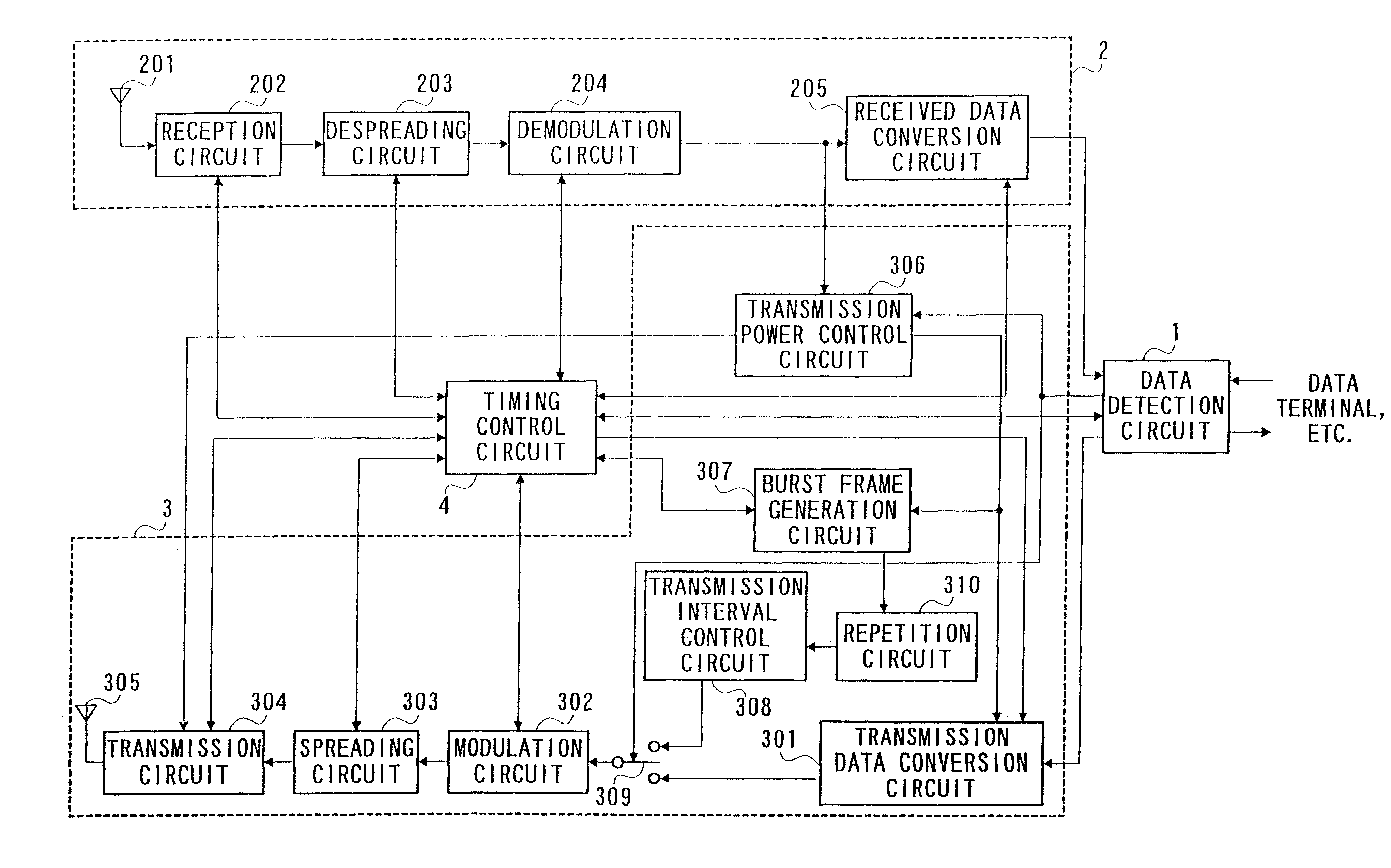
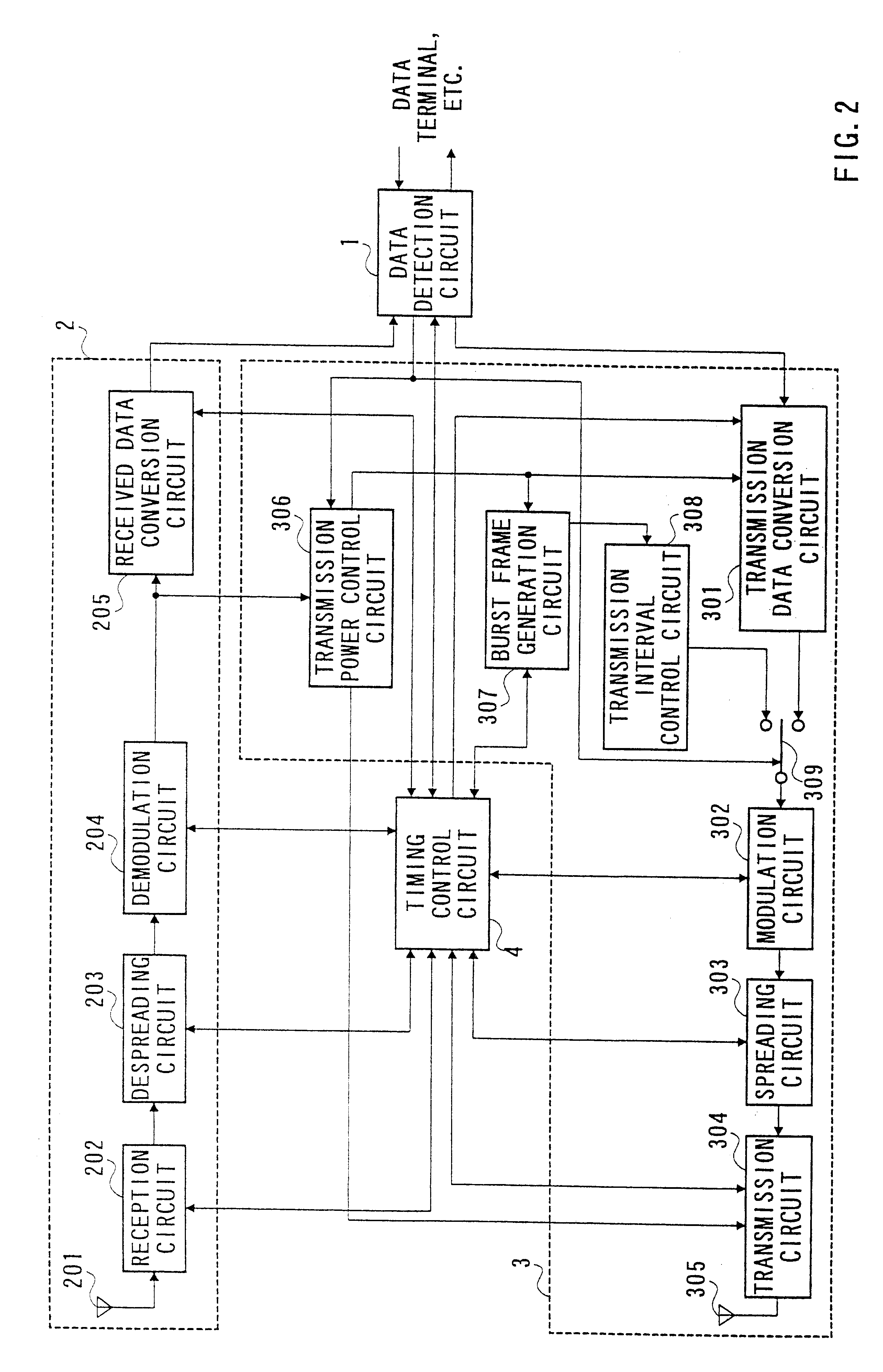
FIG. 2 is a block diagram showing the configuration of a CDMA mobile station apparatus in Embodiment 1 of the present invention.
The CDMA mobile station apparatus shown in FIG. 2 mainly comprises data detection circuit 1 that carries out data transmission / reception with a data terminal, data reception section 2 that processes a received radio signal, data transmission section 3 that processes data to be transmitted by radio, and timing control circuit 4 that controls whole timing and sequence of signal processing.
Data reception section 2 comprises reception antenna 201 that receives a radio signal, reception circuit 202 that converts the frequency of the received signal to a baseband signal, despreading circuit 203 that performs the correlation detection on the baseband signal and extracts data directed to the own station, demodulation circuit 204 that demodulates the data directed to the own station, and received data conversion circuit 205 that separates the demodulated data into a...
embodiment 2
is an embodiment which performs repetition processing on burst data at the end of transmission.
FIG. 4 is a block diagram showing the configuration of a CDMA mobile station apparatus in Embodiment 2. In the CDMA mobile station apparatus shown in FIG. 4, the same components as those in FIG. 2 are assigned the same numbers and their explanations are omitted.
FIG. 5 is a timing chart showing the transmission timing of data of the CDMA mobile station apparatus in Embodiment 2. FIG. 5A is a timing chart showing the transmission timing of data during data transmission and FIG. 5B is a timing chart showing the transmission timing of data on transmission standby. Since the transmission timing of data during data transmission and on transmission standby is the same as in FIG. 3, its explanation is omitted.
In comparison with FIG. 2, the CDMA mobile station apparatus shown in FIG. 4 is provided with repetition processing circuit 310 added to data transmission section 3.
Repetition processing circ...
embodiment 3
is an embodiment which transmits burst data with a transmission power value extracted from the received data when the base station apparatus cannot transmit TPCs during non-cyclic transmission.
FIG. 6 is a block diagram showing the configuration of a CDMA mobile station apparatus in Embodiment 3 of the present invention. In the CDMA mobile station apparatus shown in FIG. 6, the same components as those in FIG. 2 are assigned the same numbers as in FIG. 2 and their explanations are omitted.
FIG. 7 is a timing chart showing the transmission timing of data of the CDMA mobile station apparatus in Embodiment 3. FIG. 7A is a timing chart showing the transmission timing of data during data transmission. FIG. 7B is a timing chart showing the transmission timing of data on transmission standby. Since the transmission timing of data during data transmission and on transmission standby is the same as in FIG. 3, its explanation is omitted.
In comparison with FIG. 2, the CDMA mobile station apparat...
PUM
 Abstract
Description
Claims
Application Information