Gravimetric rotation sensors: dead reckoning, velocity, and heading sensor system for vehicle navigation systems

a technology of heading sensor and gravity rotation sensor, which is applied in the direction of digital computer details, instruments, roads, etc., can solve the problems of low resolution of ordinary prior art speed pulse system, and achieve the effect of reducing the significance of missed data and increasing precision

Inactive Publication Date: 2002-10-15
WEINBRENNER RICHARD L
View PDF24 Cites 68 Cited by
  • Summary
  • Abstract
  • Description
  • Claims
  • Application Information

AI Technical Summary

Benefits of technology

Furthermore, special care in choosing the formatting and inclusion of certain data can reduce the significance of missed data. Each sensor module maintains a clock and also a wheel position, which contains the positions up to some number of revolutions of the wheel, with a resolution of a small fraction of a wheel rotation. In this case, even if a data transmission is corrupted or otherwise missed, the receiver will, at the next transmission, have the true position of the wheel and the time stamp of that position.
Also the timestamp at the time of transmission of the data is sent so that the receiver can monitor the sensor clock to further increase the precision. This also allows the navigation system to coordinate the signals from this invention with other sensor information such as GPS.

Problems solved by technology

Additionally, the ordinary prior art speed pulse system offers very low resolution.

Method used


Image

  • Gravimetric rotation sensors: dead reckoning, velocity, and heading sensor system for vehicle navigation systems
  • Gravimetric rotation sensors: dead reckoning, velocity, and heading sensor system for vehicle navigation systems
  • Gravimetric rotation sensors: dead reckoning, velocity, and heading sensor system for vehicle navigation systems

Examples


Embodiment Construction

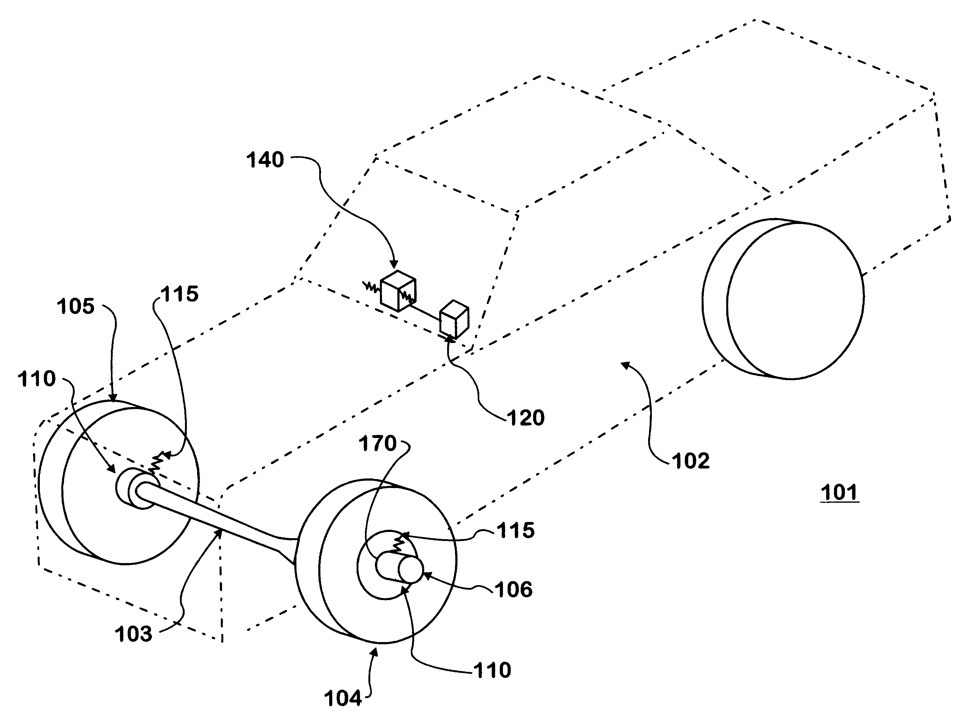
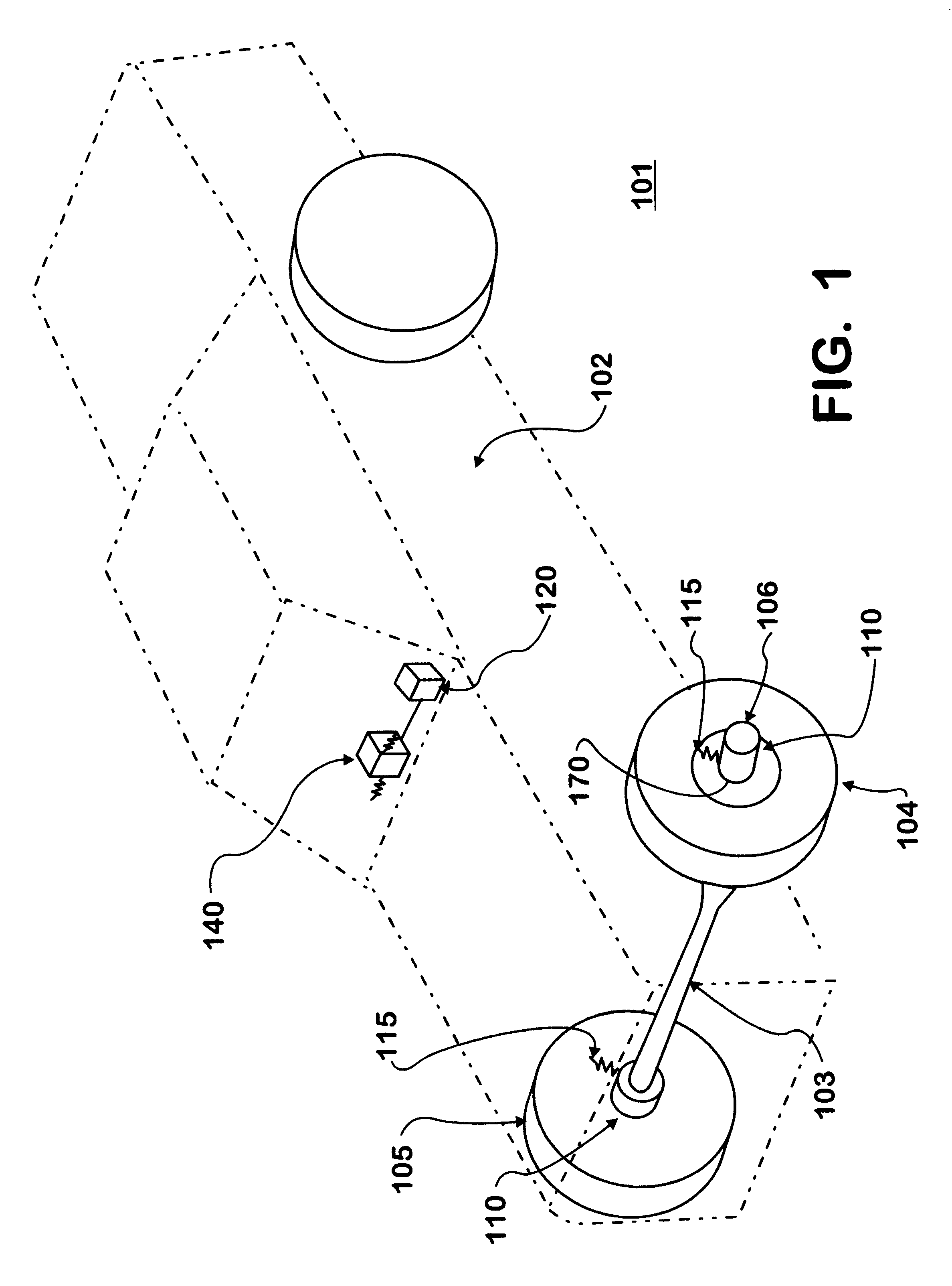
A mobile vehicle 101 is shown in FIG. 1. The vehicle 101 has an installed gravimetric rotational wheel sensor 110, and a receiver 140 for communication with an onboard Global Positioning System (GPS) navigation system 120 made in accordance with this invention. The vehicle 101 has a body 102 engaged to at least a front axle 103. The front axle 103 engaged to a left front steerable wheel 104 and a right front steerable wheel 105. Each of these wheels has an inner hub 106 for mounting to the front axle 103. FIGS. 1A to 7 show the rotational wheel sensor 110 and portions of the navigation system 120.

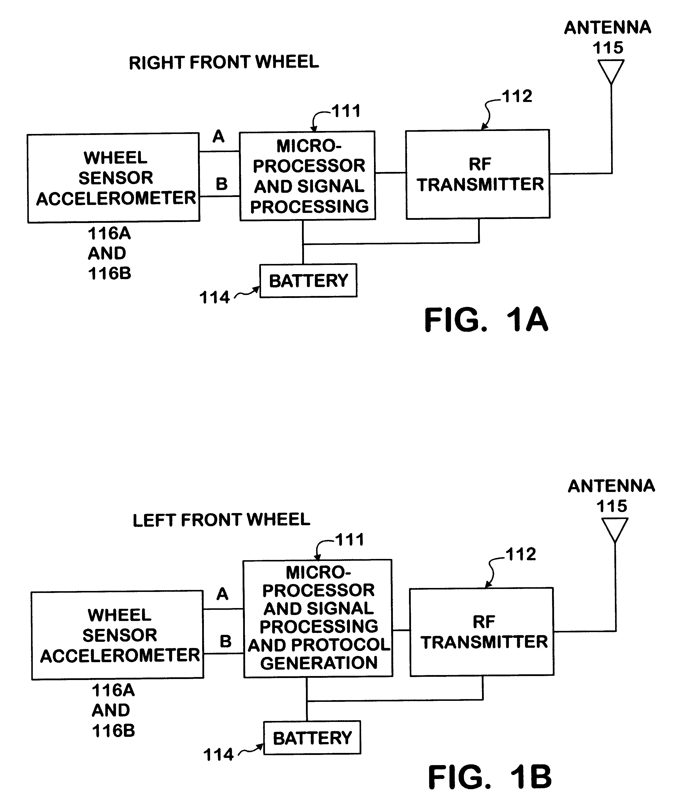
FIGS. 1A and 1B each depict block diagrams of a portion of the navigation system 120 which contains at least one rotational gravimetric wheel sensor 110 mounted onto the right and left front wheels, respectively. The wheel sensors 110 may be mounted to the inner hub 106 of the wheels. Each of the wheel sensor's 110 outputs are received by a microprocessor-based electronic circuit 111, which...


PUM


Abstract

A rotational sensor for use with an in-vehicle navigation system , a navigation system that uses the sensor, and a vehicle with the sensor installed. The rotational sensor is created by placing two gravitational accelerometers configured at 90 degrees with respect to one another and mounted at the center of a vehicle wheel. As this resulting sensor is rotated, sine and cosine signals with a quadrature relationship are generated with respect to the earth's gravity vector, from which both rotation and direction of rotation can be determined. These signals may then allow the counting of the turns of the wheel, thus estimating the distance and the rate at which the vehicle has moved. A self-contained version of this device including a transmitter can relay this information to a receiving unit located within the vehicle. When one of these devices is located on each of the steerable wheels of the vehicle, the relative heading-direction of the vehicle may also be estimated.

Description

This invention relates to a rotational sensor for use with an in-vehicle navigation system, a navigation system that uses the sensor, and a vehicle with the sensor installed. The rotational sensor is created by placing two gravitational accelerometers configured at 90 degrees with respect to one another or otherwise out of synch and mounted at or near the center of a vehicle wheel or mounted at a given radius from the center of the wheel. As this resulting sensor is rotated, sine and cosine signals with a quadrature relationship are generated with respect to the earth's gravity acceleration force vector, from which both rotation displacement and direction of rotation displacement can be determined. These signals may then allow the counting of the turns of the wheel, thus estimating the distance and the rate at which the vehicle has moved. A self-contained version of this device including a transmitter can relay this information to a receiving unit located within the vehicle. When on...

Claims


Application Information

Patent Timeline
Patent Type & Authority Patents(United States)
IPC IPC(8): G01P15/08G01P3/02G01C21/26G01P3/16
CPCG01C21/26G01P3/16G01P13/04G01P15/08
Inventor WEINBRENNER, RICHARD L.
Owner WEINBRENNER RICHARD L
Why Eureka
Try Eureka