Pump dispenser

Inactive Publication Date: 2002-10-22
NOIBERUKU
View PDF6 Cites 8 Cited by
  • Summary
  • Abstract
  • Description
  • Claims
  • Application Information

AI Technical Summary

Benefits of technology

According to the present invention, since a cam mechanism including the guide member and the follower is used in rotating, advancing and retracting the pump-driving shaft without using a ball screw, high-speed rotation, i.e. high-speed discharge is possible while improving durability.
Further, since only a single plunger insert hole and plunger are provided, the discharge motion is conducted by rotating the pump-driving shaft, i.e. the pump block, for one time, so that the discharge motion of each time can be made identical, thereby improving accuracy of discharge amount of each time.
Further, since the discharge amount can be adjusted by adjusting the inclination angle of the guide member in proportion to the inclination angle, the discharge amount can be more easily adjusted and changed as compared to the arrangement using a cam mechanism, thereby enhancing usability of the dispenser.
According to the above arrangement, since the inclination angle of the guide member can be adjusted only by moving the other end of the guide member in the axial direction of the pump-driving shaft by the discharge controller, the discharge amount can be easily adjusted.
According to the above arrangement, the condition when follower shaft is close to the fixed shaft, i.e. when the pump-driving shaft (and the plunger) is the most adjacent to the valve block, can be fixed. Accordingly, by setting the plunger tip to be at the level of the end surface of the plunger insert hole of the pump block at the above position, the dead space when the plunger goes the closest toward the valve block can be reduced, thereby preventing residence of the liquid in the plunger insert hole. Further, the adjustment range of the stroke when the guide member is inclined can become the widest, so that the adjustment range of the discharge amount can be enlarged.
With the micrometer, the discharge amount can be set using the scale of the micrometer, and the setting work can be easily conducted with high accuracy.

Problems solved by technology

However, since discharge accuracy is not so high and minute discharge control is difficult according to such arrangement, a pump dispenser has come to be used in response to such demand.
Though the dispensers have higher accuracy than dispensers other than pump-type, further improvement in accuracy and minute discharge required for very small amount discharge dispenser used for medicine analyzer etc. and a dispenser for discharging adhesive for bonding IC chips in semiconductor manufacture line has been difficult.
However, since sealing structure becomes so complicated that it is difficult to avoid in-liquid pump structure.
Though the discharge accuracy can be greatly improved in the above (3) arrangement, sealing structure becomes complicated.
Hei 9-324743, velocity (time per one discharge) is difficult to be increased and durability thereof is inferior.
Accordingly, two rotations and stop movements are required per one cycle of discharge movement, thereby limiting reduction of operation time per one cycle.
Further, in the above dispenser, since a ball screw is used to advance and retract the plunger relative to the pump block, the operation time is difficult to be reduced and, when the operation time is reduced, durability thereof is deteriorated.
Specifically, though the ball screw has to be advanced and retracted at a high speed in order to reduce discharge time, it is difficult for a ball screw to conduct such short-distance reciprocal movement at a high speed, and there can be great abrasion, thereby deteriorating durability.

Method used


Image

  • Pump dispenser
  • Pump dispenser
  • Pump dispenser

Examples


Embodiment Construction

)

An embodiment of the present invention will be described below with reference to attached drawings.

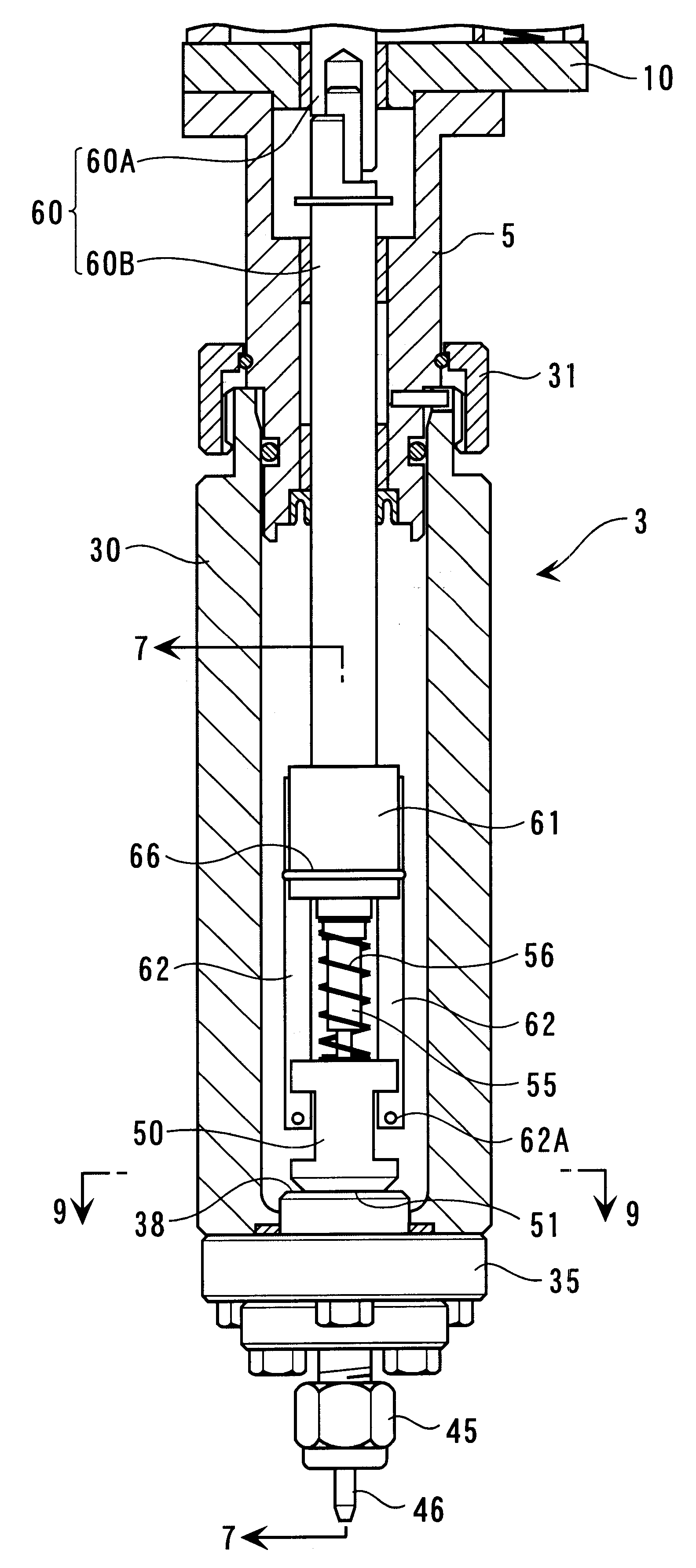
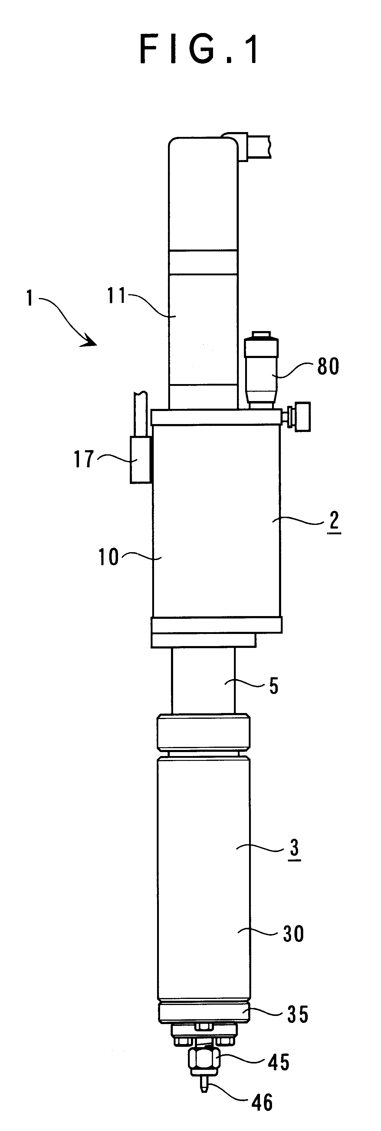
FIG. 1 shows a front elevation of a dispenser 1 according to an embodiment of the present invention. The dispenser 1 includes a driving section 2 provided with a driving mechanism and a pump section 3.

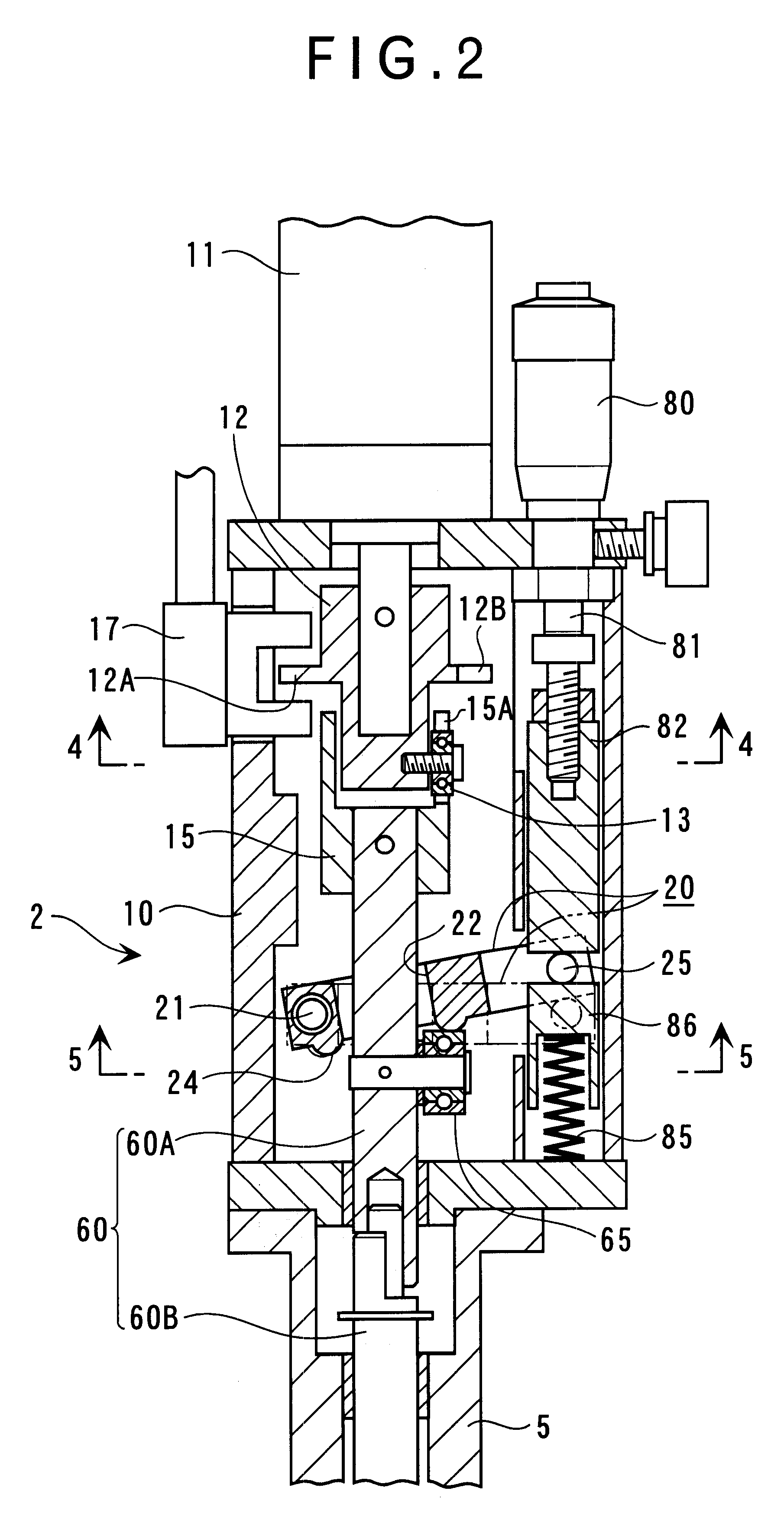
As shown in FIG. 2, the driving section 2 has a body 10 formed in a box-shape with a plurality of plates and blocks, and a motor 11 fixed to the body 10. A servo-motor and a stepping motor are used for the motor 11, which is capable of controlling per one rotation using a below-described rotary position detecting sensor 17 and a position detecting sensor such as an encoder installed in the servo-motor.

A rotation interlocking member 12 formed in approximate cylinder is fixed to an output shaft of the motor 11. As shown in FIG. 4, a flange 12A provided with a notch 12B at a part thereof is formed on the rotation interlocking member 12. The rotary position detecting sensor 17 is located at ...


PUM


Abstract

A pump dispenser includes: a valve block having a first slide contact surface, a discharge opening and a suction opening; a pump block having a second slide contact surface and a plunger insert hole; a plunger slidably inserted to the plunger insert hole; a pump-driving shaft for rotating the pump block to advance and retract the plunger; and a motor for controllably rotating the pump-driving shaft per one rotation, the pump-driving shaft being attached with a roller, the pump dispenser further having a guide member capable of adjusting inclination angle thereof relative to a reference surface orthogonal with an axis of the pump-driving shaft, the guide member guiding the roller moving in accordance with a rotation of the pump-driving shaft to advance and retract the pump-driving shaft.

Description

1. Field of the InventionThe present invention relates to a pump dispenser for sucking and discharging liquid by virtue of reciprocal movement of a plunger.2. Description of Related ArtConventionally, a liquid dispenser (liquid discharging device) mainly has an arrangement where liquid packed in a syringe is pressurized for a short time and pushed by air or a valve is opened for a short time after pressurizing the liquid.However, since discharge accuracy is not so high and minute discharge control is difficult according to such arrangement, a pump dispenser has come to be used in response to such demand.An easily-controllable pump dispenser such as gear pump in proportion to rotation, a viscosity pump, a screw pump and a positive-load pump using an automatic valve is used as the above pump dispenser. Though the dispensers have higher accuracy than dispensers other than pump-type, further improvement in accuracy and minute discharge required for very small amount discharge dispenser ...

Claims


Application Information

Patent Timeline
IPC IPC(8): G01F11/02
CPCG01F11/023
Inventor OGAWA, KENJI
Owner NOIBERUKU
Why Eureka
Try Eureka