Positioning stage

Inactive Publication Date: 2002-10-22
GOVERNMENT OF THE US REPRESENTED BY THE SEC OF COMMERCE THE
View PDF6 Cites 63 Cited by
  • Summary
  • Abstract
  • Description
  • Claims
  • Application Information

AI Technical Summary

Benefits of technology

One object of the present invention is to provide an improved technique for

Problems solved by technology

However, if there is a misalignment of the fiber ends, this process can take as long as forty-five minutes to an hour.
Conventional assembly of opto-electronic devices can, as discussed above, require substantial worker time and therefore be quite costly.
Positioning devices currently available do not provide the precision and range of motion required in these and other technological fields.
However, the resulting movement in each of the X and Y directions is not purely linear.
Rather, the proposed structure introduces a yaw which is unacceptable for precision manufacturing applications.
Known prior art positioning devices cannot eliminate rotational cross talk unless additional actuators are included in the device to apply counterbalancing rotation and thereby ensure pure linear movement.
These actuators add undesirable complexity and costs to the devices.
Additionally, complex control algorithms must be developed and used to operate multiple actuators in concert to compensate for the cross talk.
In the proposed micro-positioning stage discussed above, as well as other proposed stages, the rotational cross talk error is inherent in the design.
That is, applying a force intended to move a stage in one direction necessarily produces an unintended rotation.
Conventional deformable structure micro-positioners use sensors which are typically located at a position which results in inaccurate measurement of the true stage displacement.
For example, when a force is applied to an epoxy connection between the actuator and the

Method used


Image

  • Positioning stage
  • Positioning stage
  • Positioning stage

Examples


freedom embodiment

Four-Degrees of Freedom Embodiment

A fourth degree of freedom may be added to a three-degree of freedom deformable structure micro-positioner by including an actuator placed on the moving stage. This actuator raises and lowers an object placed upon the deformable structure micro-positioner. FIG. 17 shows a three-degree of freedom positioner with actuator 1701 placed upon the moving stage 1702 to obtain the fourth degree of freedom. Upper stage 1703 is placed on top of actuator 1701. Unlabeled components are identical to those depicted in FIG. 16 and described above.

embodiment

Reduced Size Embodiment

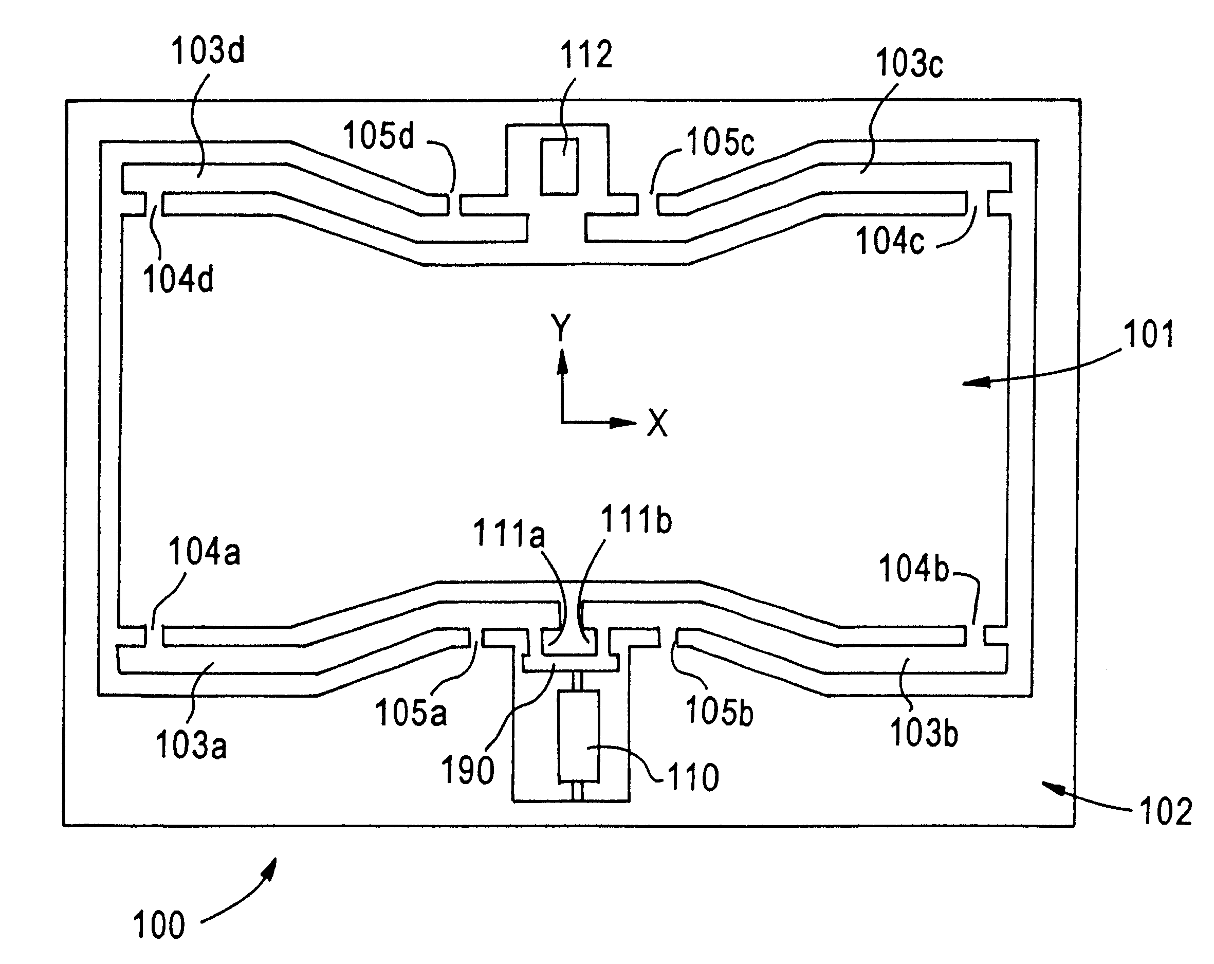
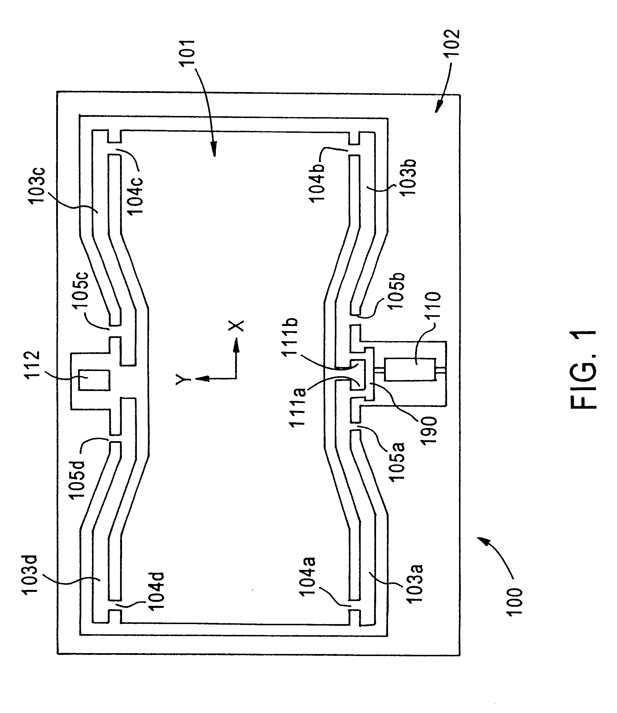
The size of the above deformable structure parallel cantilever biaxial micro-positioning stages may be reduced as much as 60 percent. FIG. 6 depicts a reduced size embodiment 600. Shown is a one-degree of freedom device for movement in the direction of the Y-axis of the moving stage 607. As should be understood, the design may be expanded to achieve movement along the X-axis and to impart desired rotation to the moving stage. Also, two actuators may be used on any axis of movement. Unlabeled components are identical to those in FIG. 1.

The reduced size design maintains the symmetry of the previously described embodiments. Instead of four levers connecting the moving stage to the support structure 601, nested levers are used. Each of the four levers of the one-degree of freedom micro-positioner described above is replaced with two levers. Actuator 602 moves both levers 603a and 603b. Lever 603a pivots about flexure 604a. Lever 603b pivots about flexure 604b. In ...


PUM

PropertyMeasurementUnit
Forceaaaaaaaaaa

Abstract

A positioning device and method for positioning objects is provided. The device includes a movable stage and a pair of levers. The pair of levers is symmetric about a first axis of the movable stage. Additionally, the pair of levers is parallel to a second axis of the movable stage. This second axis is perpendicular to the first axis. Each of the pair of levers applies a force to the movable stage. Each of the pair of levers moves in an arc. The two levers move in opposite directions along their respective arc. The two arcs are symmetrical about an axis of the movable stage.

Description

The present invention relates to positioners for positioning objects, and more particularly to a deformable positioning stage.Assembly of optic-electronic devices requires precision alignment of optical fibers with lasers or sensors and then bonding. A worker looking through a microscope at the end of a fiber conventionally executes this precision alignment and bonding process.The alignment and bonding process can take as little as five minutes. However, if there is a misalignment of the fiber ends, this process can take as long as forty-five minutes to an hour. Misalignment often occurs because the fibers are subject to other than pure linear movement during the alignment process. Accordingly, a need exists for an improved alignment process which will reduce, if not eliminate, misalignment of a fiber end.It is likely that in the next ten years the use of opto-electronic devices will spread to automobiles and every phone and computer manufactured in the United States, resulting in a...

Claims


Application Information

Patent Timeline
IPC IPC(8): B23Q1/48B23Q1/34B23Q1/62B23Q1/26B23Q1/25G02B26/00G02B21/26G02B21/24G02B7/00G02B6/42
CPCB23Q1/34B23Q1/4866B23Q1/621G02B6/4226G02B7/005G02B26/00G02B21/26Y10T29/53974Y10S977/773Y10S977/932Y10S977/724
Inventor AMATUCCI, EDWARD G.DAGALAKIS, NICHOLAS G.MARCINKOSKI, JASONSCIRE, FREDERIC E.KRAMAR, JOHN A.
Owner GOVERNMENT OF THE US REPRESENTED BY THE SEC OF COMMERCE THE
Why Eureka
Try Eureka