Lamp reflector and method of manufacturing the same

a technology of reflector and lamp, which is applied in the direction of transportation and packaging, other domestic objects, light and heating apparatus, etc., can solve the problems of difficult to ensure the smoothness of the substrate surface, difficult to ensure the dimensional accuracy, temperature of the mold or the conditions,

Inactive Publication Date: 2002-10-29
KOITO MFG CO LTD
View PDF2 Cites 5 Cited by
  • Summary
  • Abstract
  • Description
  • Claims
  • Application Information

AI Technical Summary

Benefits of technology

Thus, the surface smoothness and the rigidity are made compatible. That is, the viscosity of the resin in which the reinforcement materials have been kneaded and dispersed is made constant, so that a substrate--of a lamp reflector, which substrate is a molded product--having a high dimensional accuracy can be obtained.
Accordingly, the lamp reflector of present invention contributes a technically significant improvement in the quality performance of the lamp reflector which is disposed in a head lamp, a fog lamp, or the like, mounted on a two-wheel or four-wheel car, or the like. Further, the method of manufacturing the lamp reflector according to the present invention improves productivity in the process for manufacturing the lamp reflector.

Problems solved by technology

Therefore, it becomes difficult to ensure the smoothness of the substrate surface, or it becomes difficult to ensure dimensional accuracy.
To prevent such difficulties, there was a disadvantageous technique wherein the temperature of a mold or the conditions of injection molding always had to be controlled in accordance with the properties of the resin.
As a result, there arose a problem that fog generated in the concave portions 103a had a bad influence on the light distribution performance.
On the contrary, if the content of synthetic calcium carbonate whiskers or synthetic calcium carbonate is too much, the rigidity will be ensured, but the surface smoothness will deteriorate.
In addition, because PPS resin is reduced relatively, the flowability of molding resin will be lowered so that injection molding will be difficult.
As a result, there is no irregular reflection due to the under coat layer, as there is in the related art wherein the under coat layer is gathered in step portions, which has been problematic hitherto.

Method used


Image

  • Lamp reflector and method of manufacturing the same
  • Lamp reflector and method of manufacturing the same
  • Lamp reflector and method of manufacturing the same

Examples


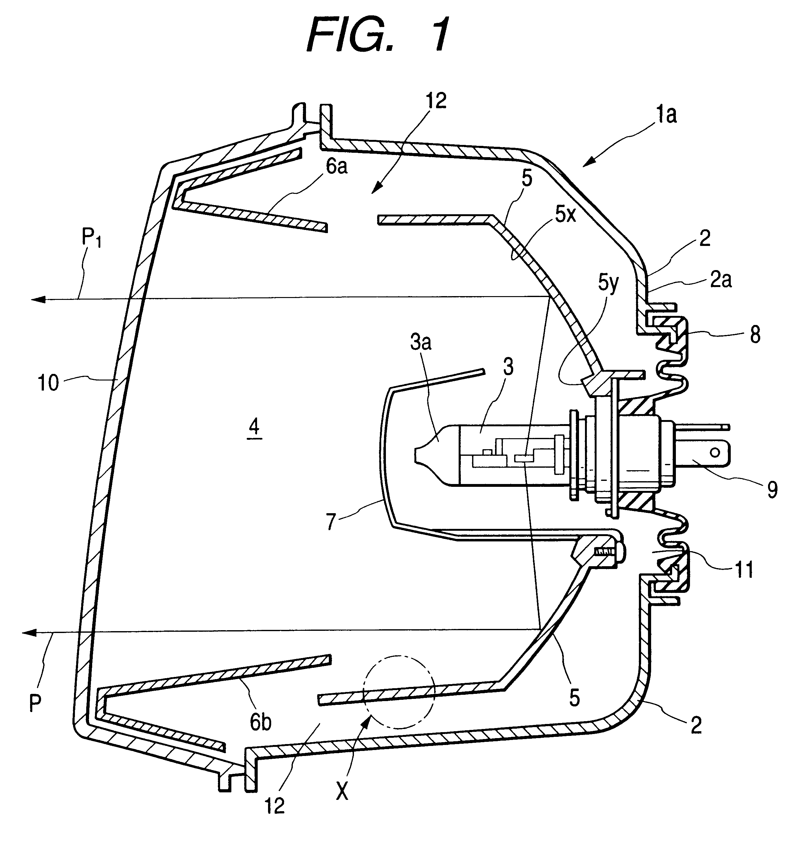
Embodiment Construction

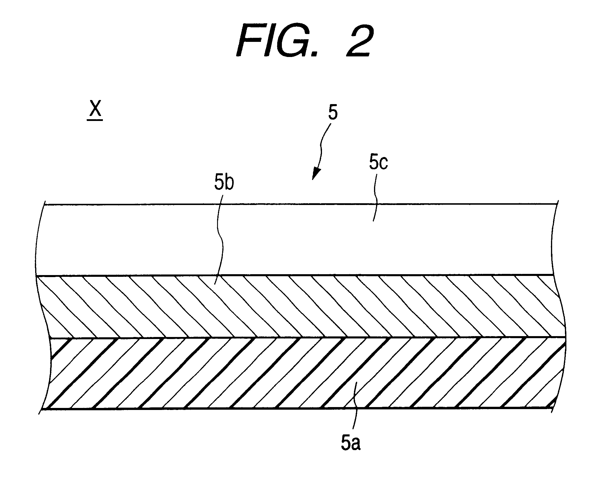
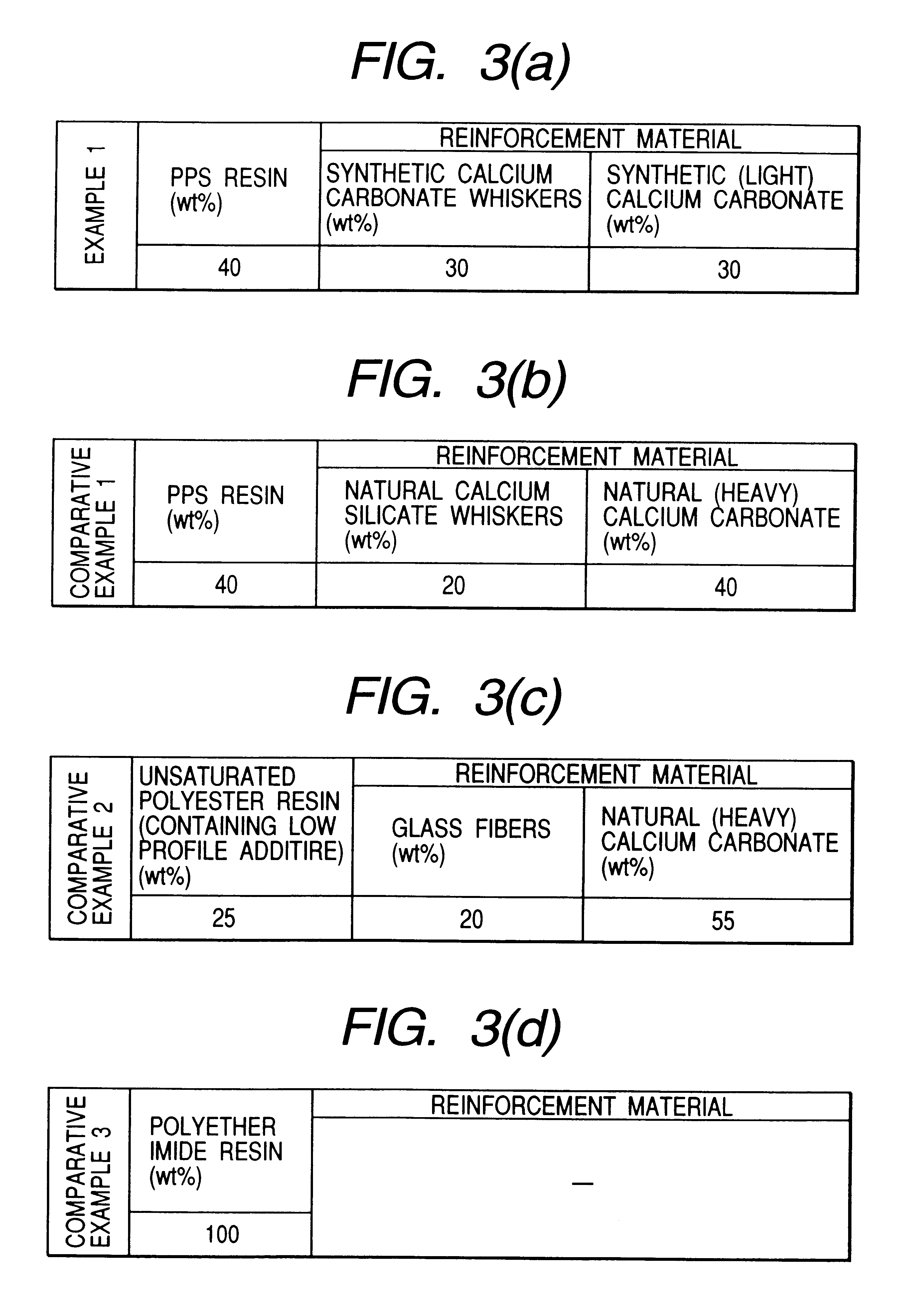
, made according to the present invention, had a substrate 5a (with no under coat layer) with a composition of 40 weight % (hereinafter referred to as "wt %") of PPS resin, 30 wt % of synthetic calcium carbonate whiskers and 30 wt % of synthetic (light) calcium carbonate as shown in FIG. 3(a). Comparative examples 1 to 3 had substrates with compositions shown in FIGS. 3(b) to (d), respectively.

The lamp reflectors of Example 1 and Comparative examples 1 to 3 used in this test were manufactured as follows. The components shown in FIGS. 3(a) to 3(d) were kneaded and dispersed; the substrates of the lamp reflectors were formed by the method of injection molding; common activation treatment was applied to the respective substrates so as to form metal coatings thereon; and then top coats were provided on respective metal coatings.

A description of specific methods used in this test will now be set forth. First, the surface smoothness was measured with a surface profilometer "DEKTAK 3030" m...


PUM

PropertyMeasurementUnit
particle sizeaaaaaaaaaa
widthaaaaaaaaaa
widthaaaaaaaaaa

Abstract

A lamp reflector having a substrate in which desired surface smoothness and rigidity are ensured, while the dimensional accuracy is high. Also, a method of manufacturing such a lamp reflector. In order to ensure surface smoothness, rigidity, and high dimensional accuracy, the lamp reflector is provided with a substrate made of a composition containing at least polyphenylene sulfide resin (PPS resin), synthetic calcium carbonate whiskers, and synthetic calcium carbonate (CaCO3). And the method for manufacturing this lamp reflector includes injection molding using high-pressure gas.

Description

1. Field of the InventionThe present invention relates to a lamp reflector, particularly a lamp reflector suitable for a head lamp, a fog lamp, or the like, mounted on a two-wheel or four-wheel vehicle, or the like; and a lamp reflector manufacturing method. More particularly, the present invention relates to a lamp reflector which has a substrate high in surface smoothness due to the material composition of a substrate constituting the lamp reflector, and also relates to a method for manufacturing such a lamp reflector.2. Description of the Related ArtCurrently, thermoplastic resin, for example, polyphenylene sulfide resin (PPS resin) is used as a basic material (base resin) of a substrate constituting a lamp reflector for use in a head lamp or a fog lamp for a vehicle. A reinforcement material such as whiskers, calcium carbonate powder, or the like, is kneaded and dispersed into the basic material in order to enhance the rigidity and increase the molding dimensional stability and ...

Claims


Application Information

Patent Timeline
Patent Type & Authority Patents(United States)
IPC IPC(8): B29C45/00B29C45/17F21V7/22F21V7/00G02B5/08F21W107/10F21Y101/00
CPCB29C45/0001B29C45/174F21S48/1394F21S48/238F21S48/25F21V7/22B29L2011/0083F21S41/37F21S43/33F21S43/50F21V7/24F21V7/28
Inventor YOSHIMOTO, YUJIIKEDA, TOSHIMASATOKI, JUNJI
Owner KOITO MFG CO LTD
Why Eureka
Try Eureka