
Dispersion-compensating optical fiber, and, optical transmission line and dispersion-compensating module respectively including the same

a technology of optical fiber and dispersion slope, which is applied in the direction of optical fibers with desired dispersion, cladded optical fibres, instruments, etc., can solve the problem of reducing the absolute value of accumulated chromatic dispersion in the optical transmission line in a wide band, smf-based dispersion-compensating optical fibers are not sufficient to compensate for dispersion slope, and large bending loss in fundamental-mode ligh

Inactive Publication Date: 2002-11-05
SUMITOMO ELECTRIC IND LTD
View PDF14 Cites 36 Cited by
  • Summary
  • Abstract
  • Description
  • Claims
  • Application Information

AI Technical Summary

Benefits of technology

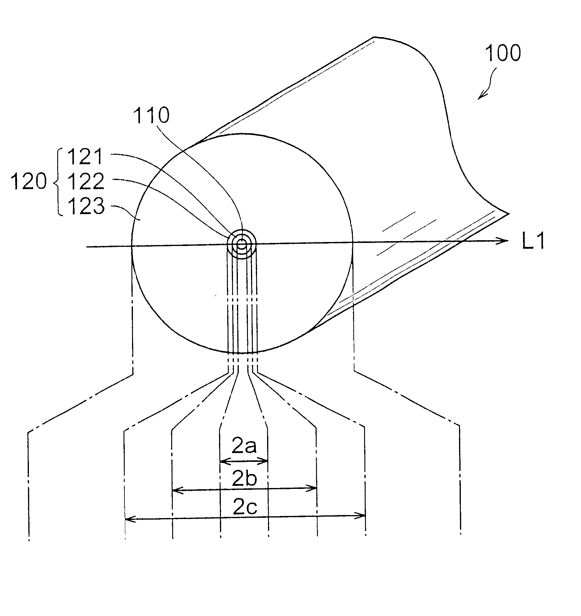
The dispersion-compensating optical fiber according to the present invention has, at a wavelength of 1550 nm, a chromatic dispersion D.sub.DCF of -40 ps / nm / km or less and a ratio (S.sub.DCF / D.sub.DCF) of dispersion slope S.sub.DCF to the chromatic dispersion D.sub.DCF of 0.005 / nm or more. By this structure, the occurrence of non-linear phenomenon can be effectively prevented because an effective area can be easily expand. Preferably, in the dispersion-compensating optical fiber according to the present invention, the chromatic dispersion D.sub.DCF is -100 ps / nm / km or more but -40 ps / nm / km or less, and the ratio (S.sub.DCF / D.sub.DCF) of dispersion slope S.sub.DCF to the chromatic dispersion D.sub.DCF is 0.005 / nm or more but 0.015 / nm or less. Since the chromatic dispersion D.sub.DCF is negative with a large absolute value, and the ratio (S.sub.DCF / D.sub.DCF) of dispersion slope S.sub.DCF to chromatic dispersion D.sub.DCF lies within the numerical range mentioned above, this dispersion-compensating optical fiber can compensate for the chromatic dispersion and dispersion slope of a dispersion-shifted optical fiber in a wide band including a wavelength of 1550 nm by a short length.
Still further, the dispersion-compensating optical fiber according to the present invention preferably has, at a wavelength of 1550 nm, a chromatic dispersion D.sub.DCF of -40 ps / nm / km or less, a ratio (S.sub.DCF / D.sub.DCF) of dispersion slope S.sub.DCF to the chromatic dispersion D.sub.DCF of 0.005 / nm or more, and a transmission loss of 0.5 dB / km or less. This dispersion-compensating optical fiber not only can compensate for the chromatic dispersion and dispersion slope of a dispersion-shifted optical fiber by a short length, but also yields a low loss even when formed into a cable or module.

Problems solved by technology

In general, since it is hard to achieve in an optical transmission line using only one kind of optical fiber, a plurality of kinds of optical fibers have been connected so as to construct an optical transmission line, thereby lowering the absolute value of accumulated chromatic dispersion in the optical transmission line in a wide band.
The inventors have studied conventional optical transmission lines in detail and, and as a result, have found problems as follows.
However, this dispersion-compensating optical fiber for SMF is not sufficient for compensating for the dispersion slope.
Meanwhile, even upon slight bending, fundamental-mode light is likely to leak out from dispersion-compensating optical fibers for DSF in general, so that bending loss is large in the fundamental-mode light.
Consequently, transmission loss becomes greater when a dispersion-compensating optical fiber for DSF is laid as being cabled or is formed into a dispersion-compensating module as being wound like a coil.
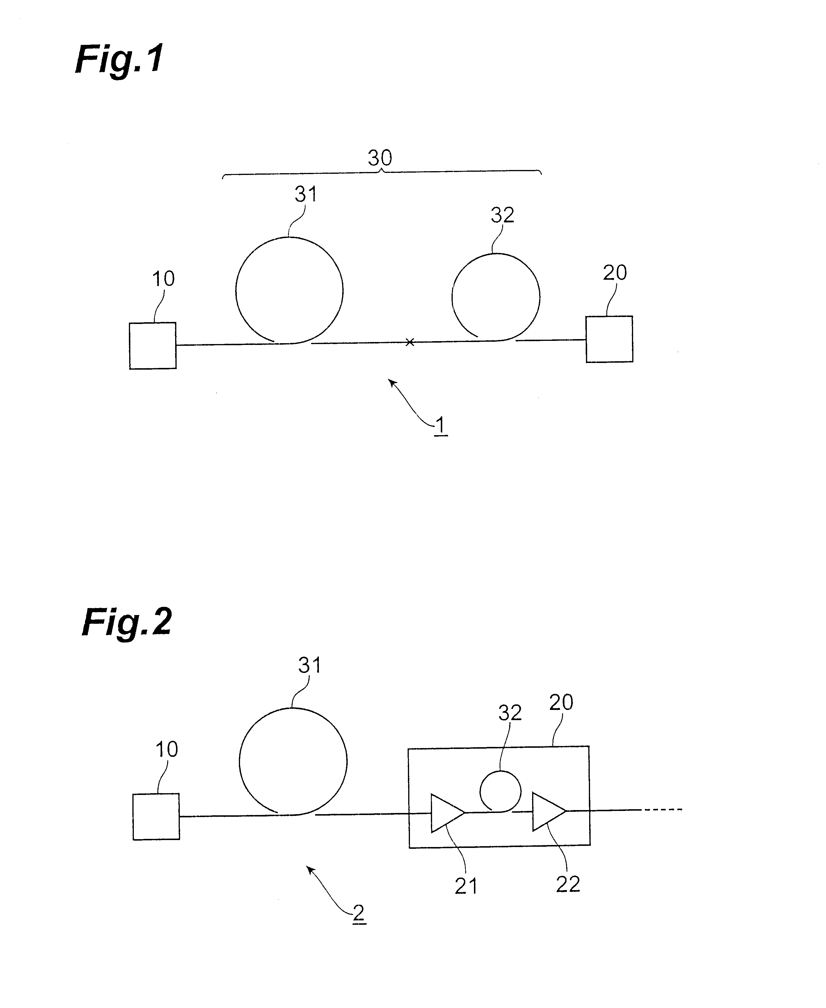
Therefore, in an optical transmission system which carries out optical communications by propagation of signals through an optical transmission line constructed by a dispersion-shifted optical fiber and a dispersion-compensating optical fiber for DSF which are connected to each other, transmission loss is so large in the optical transmission line that its repeater section cannot be elongated, whereby higher speed and larger capacity cannot further be achieved in optical communications.
This dispersion-compensating optical fiber not only can compensate for the chromatic dispersion and dispersion slope of a dispersion-shifted optical fiber by a short length, but also yields a low loss even when formed into a cable or module.

Method used


Image

  • Dispersion-compensating optical fiber, and, optical transmission line and dispersion-compensating module respectively including the same
  • Dispersion-compensating optical fiber, and, optical transmission line and dispersion-compensating module respectively including the same
  • Dispersion-compensating optical fiber, and, optical transmission line and dispersion-compensating module respectively including the same

Examples


Embodiment Construction

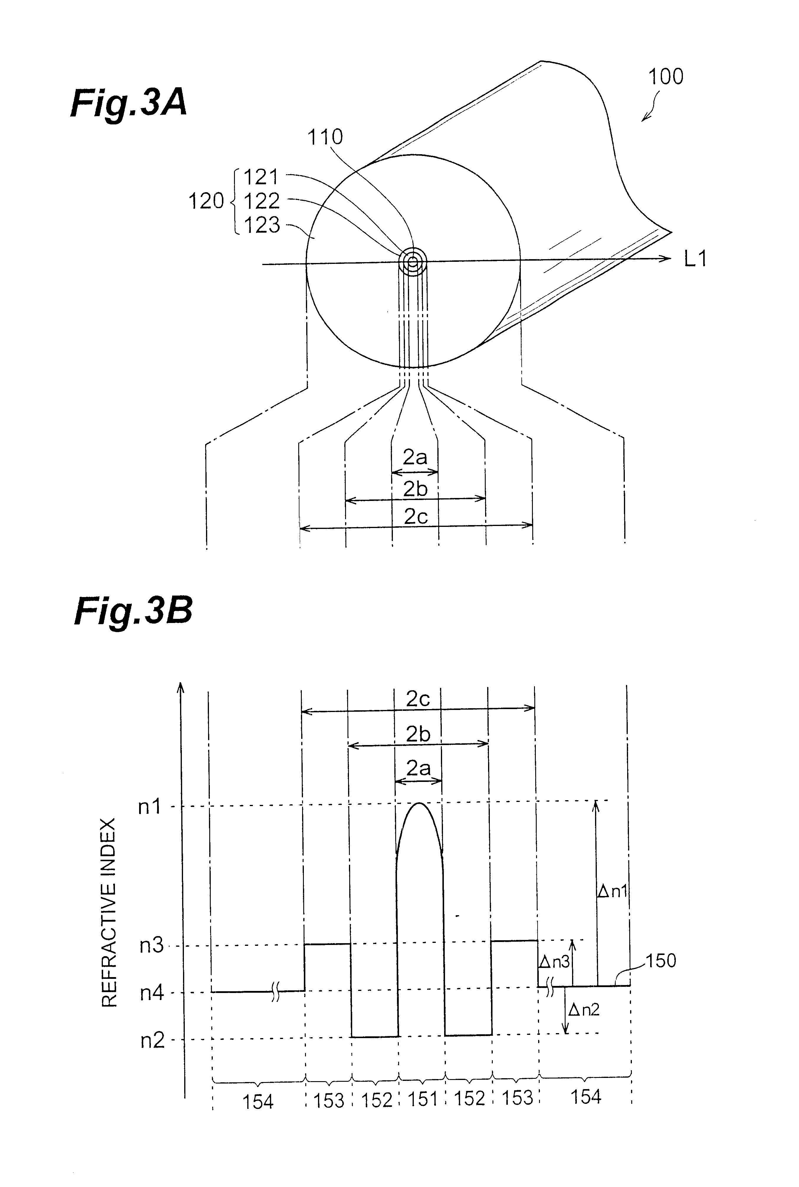
For comparison with the dispersion-compensating optical fiber of each of the above-mentioned first to seventh embodiments, the dispersion-compensating optical fiber of a comparative example will now be explained. FIGS. 17A and 17B are views showing a cross-sectional structure of the dispersion-compensating optical fiber according to the comparative example and its refractive index profile, respectively. This comparative example 200 comprises a core region 210 extending along a predetermined axis and a cladding region 220 provided so as to surround the outer periphery of the core region 210. The core region 210 has a refractive index n.sub.1 and an outer diameter of 2a. Further, the cladding region 220 comprises a first cladding 221 having a second refractive index n.sub.2 (n.sub.2,

The refractive index profile 250 shown in FIG. 17B indicates respective refractive indices at individual parts on the line L2 in FIG. 17A, such that areas 251, 252, and 253 in the refractive ind...


PUM


Abstract

The invention is directed to a dispersion-compensating optical fiber which can compensate for the chromatic dispersion and dispersion slope of a non-zero dispersion-shifted optical fiber by a short length. The dispersion-shifted optical fiber constitutes an optical transmission line together with a dispersion-compensating optical fiber fusion-spliced thereto. The dispersion-compensating optical fiber has, at a wavelength of 1550 nm, a chromatic dispersion DDCF of -40 ps / nm / km or less and a ratio (DDCF / SDCF) of dispersion slope SDCF to the chromatic dispersion DDCF of 0.005 / nm or more.

Description

1. Field of the InventionThe present invention relates to a dispersion-compensating optical fiber which compensates for the chromatic dispersion and dispersion slope of a dispersion-shifted optical fiber, an optical transmission line including the dispersion-shifted optical fiber and dispersion-compensating optical fiber, and a dispersion-compensating module formed by winding the dispersion-shifted optical fiber like a coil.2. Related Background ArtFor achieving further higher speed and larger capacity in optical transmission systems which carry out wavelength division multiplexing (WDM) optical transmission, it is important that the absolute value of accumulated chromatic dispersion be as small as possible in a wide signal wavelength band. In general, since it is hard to achieve in an optical transmission line using only one kind of optical fiber, a plurality of kinds of optical fibers have been connected so as to construct an optical transmission line, thereby lowering the absolut...

Claims


Application Information

Patent Timeline
Patent Type & Authority Patents(United States)
IPC IPC(8): G02B6/02
CPCG02B6/02004G02B6/02261G02B6/0228G02B6/03627G02B6/03644G02B6/29377
Inventor KATO, TAKATOSHIHIRANO, MASAAKI
Owner SUMITOMO ELECTRIC IND LTD
Learn More