Optical probe having and methods for difuse and uniform light irradiation

a technology applied in the field of optical probes and optical methods, can solve the problems of inability to achieve full contact, low depth of field, and inability to accurately detect the light energy returning from the targ

a technology applied in the field of optical probes and optical methods, can solve the problems of inability to achieve full contact, low depth of field, and inability to accurately detect the light energy returning from the targ

US6487440B2Inactive Publication Date: 2002-11-26LIFESPEX

Image

  • Optical probe having and methods for difuse and uniform light irradiation
  • Optical probe having and methods for difuse and uniform light irradiation
  • Optical probe having and methods for difuse and uniform light irradiation

Examples


Embodiment Construction

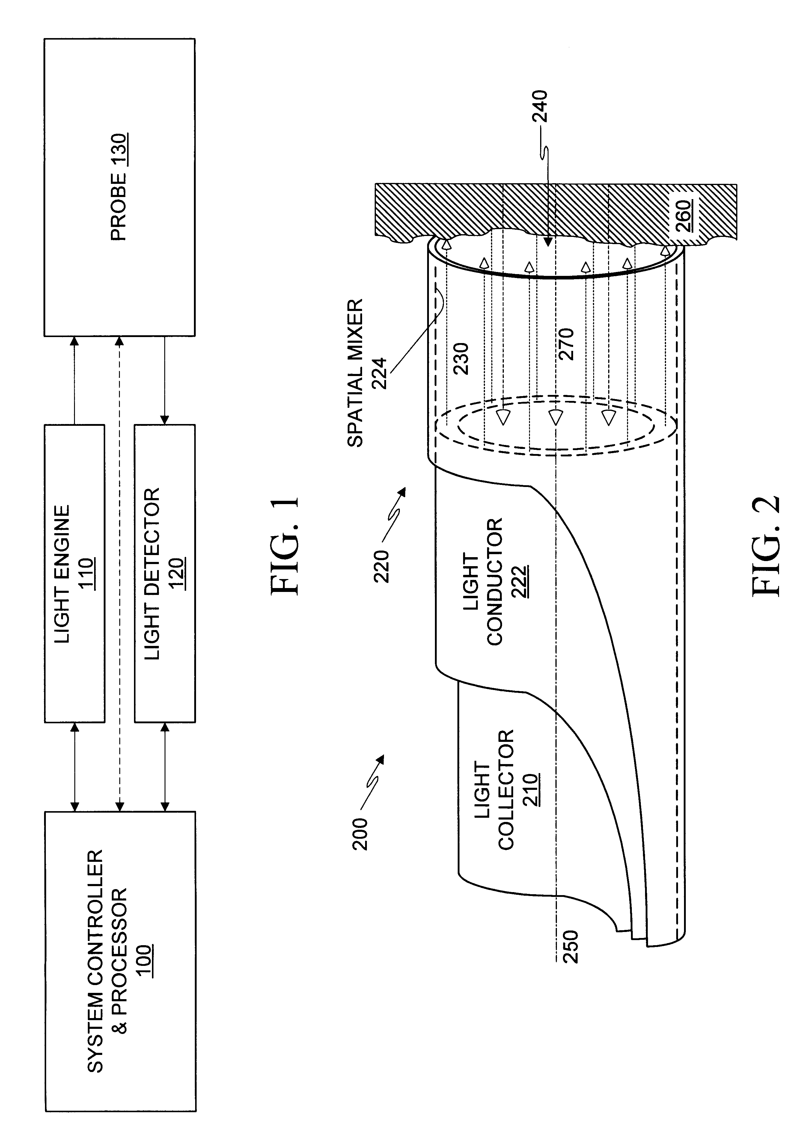
FIG. 1 shows schematically the basic elements of an illustrative optical system for the examination of materials. As used herein, optics refers to the branch of physics that deals with the generation, propagation, and detection of electromagnetic radiation having wavelengths greater than x-rays and shorter than microwaves, and light refers to electromagnetic radiation at one or more wavelengths (narrowband, broadband, or any combination thereof) anywhere in the electromagnetic spectrum greater than x-rays and shorter than microwaves. An optical probe 130 is used to irradiate the material being examined (i.e. the target) and for collecting radiation from the target due to the irradiation. A system controller and processor 100 controls the various operations performed by the system and processes various characteristics of the radiation image collected from the target to obtain multispectral indications about various properties of the target material. Where the material is mammalian ti...


PUM


Abstract

A variety of optical probes and methods have utility in the examination of various materials, especially materials in the interior of cavities having restricted access through orifices or passageways. One type of such optical probe is elongated and includes a distal optical window, a divergent light source, a spatial mixer, and a light collector. Light from the light source is mixed in the spatial mixer to achieve uniform diffuse light in the vicinity of the optical window. The light collector receives light from the target through the spatial mixer. The optical probe may be made of two sections, a reusable section and a disposable. The disposable is elongated and contains a mounting section, an inside surface suitable for the spatial mixing of light, and an optical element which helps to seal the reusable probe section from the target.

Description

1. Field of the InventionThe present invention relates to optical probes and optical methods, some embodiments thereof being particularly related to optical probes and methods having utility in the examination of material, especially material in the interior of cavities having restricted access through orifices or passageways, and some embodiments thereof being particularly related to optical probes and methods having utility in the examination of the epithelia and other tissues of anatomical structures within the body cavities and tubular organs and viscera of mammals.2. Description of Related ArtVarious apparatus are known for optically probing the interior of cavities of living and non-living bodies. An early inspection apparatus that uses a disposable sheath and which has particular application to the human cervix is described in U.S. Pat. No. 3,945,371 entitled "Apparatus for Inspection and Sampling in Restricted Aperture Cavities Employing Fibre Optics," issued Mar. 23, 1976 t...

Claims


Application Information

Patent Timeline
26 Nov 2002
Publication
US6487440B2
IPC
G02B23/24; G02B23/26; A61B1/00; A61B1/06; A61B1/303; A61B1/307; A61B1/31
CPC
G02B23/2407; G02B23/2461; G02B23/2469
Inventors
DECKERT, CURTIS K.; HILDWEIN, ROGER L.