Controlled auto-ignition lean burn stratified engine by intelligent injection
a technology of intelligent injection and lean burn, which is applied in the direction of machines/engines, electrical control, output power, etc., can solve the problems of increasing the difficulty of auto-ignition, limiting the range at which an engine can be operated with a lean air/fuel mixture, and advancing the closing timing of the intake valv
- Summary
- Abstract
- Description
- Claims
- Application Information
AI Technical Summary
Problems solved by technology
Method used
Image
Examples
second embodiment
In a second embodiment, at least one of operating conditions including load and engine speed determines beginning of injection for second injection BOI_S. Referring to FIGS. 16 and 17, FIG. 16 provides a knock intensity variation curve 180, while FIG. 17 provides an ignition delay variation curve 182.
Curve 180 of FIG. 16 clearly indicates that if beginning of burning of gasoline fuel dispersed within fresh air content 102 advances, knock intensity becomes strong. This is because temperature and pressure become high at around top dead center of compression stroke, causing rapid burning to take place. Auto-ignition range may extend toward high load by retarding beginning of burning of gasoline fuel within fresh air content 102 as load request becomes high. In the second embodiment, engine controller 14 retards beginning of second injection as load request becomes high.
Curve 182 of FIG. 17 clearly indicates that an ignition delay becomes large as engine speed becomes high. The ignition...
third embodiment
The flow diagram of FIG. 23, generally indicated at 200, illustrates a flow of operations for carrying out control of the system of FIG. 1 according to the third preferred embodiment of the present invention. FIG. 24 is a map, stored in a non-volatile memory, containing optimum values of EGR rate against varying values of exhaust gas temperature Texh. In the third embodiment, a desired value in EGR rate is found in the map of FIG. 24 against exhaust gas temperature Texh, and inlet and outlet control devices 36 and 38 are adjusted in response to EGR rate to vary exhaust gas retaining duration (minus overlap in FIG. 4).
Flow diagram 200 of FIG. 23 is substantially the same lo as flow diagram 150 of FIG. 15. Thus, like reference numerals designate like or corresponding blocks in FIGS. 15 and 23.
However, flow diagram 200 is different from flow diagram 150 in that blocks 202, 204, and 206 have replaced blocks 160 and 162 of FIG. 15.
In FIG. 23, controller 14 input exhaust gas temperature T...
fourth embodiment
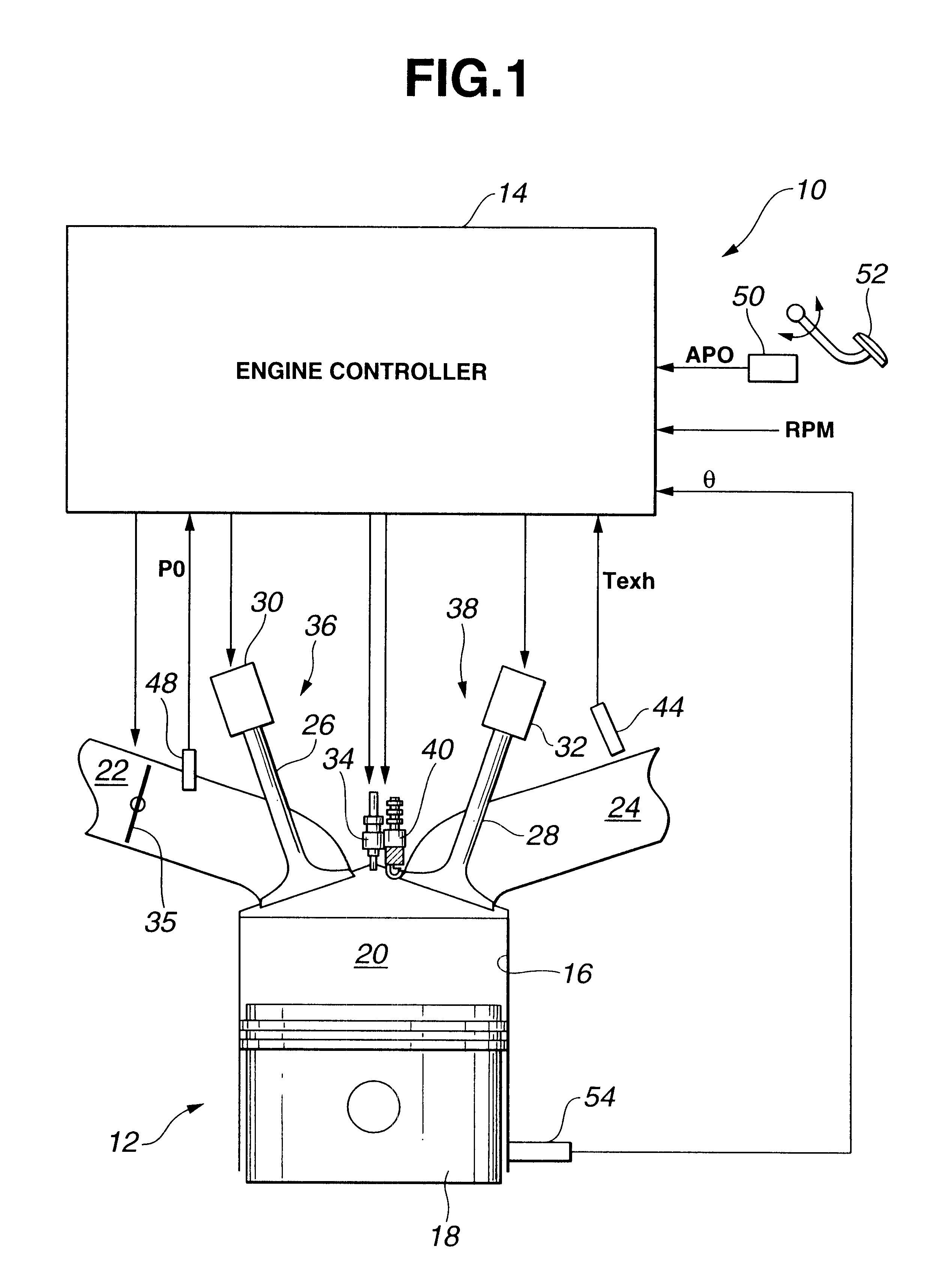
Referring to FIGS. 25-27, in a fourth embodiment, supply of exhaust gas to form exhaust gas content 106 of a combustion chamber 20 is fed from one of two exhaust ports 210 and 212 after passing through an external EGR pipe 214 as different from a technique employed in the preceding embodiments to retain exhaust gas. EGR pipe 214 has an inlet end coupled to exhaust port 212 and an outlet end coupled to an intake port 216. Intake port 216 is coupled to cylinder 16 for supplying the exhaust gas to combustion chamber 20. Another intake port 218 is coupled to cylinder 16 for supplying fresh air to combustion chamber 20 thereby to place the exhaust gas content locally within combustion chamber 20. An EGR valve 220 is provided to regulate flow through EGR pipe 214. A fuel injector 34 is located for direct injection of gasoline fuel for dispersion within fresh air content 102 during a first injection as shown in FIG. 26 and for direct injection of gasoline fuel for dispersion within exhaust...
PUM
 Abstract
Description
Claims
Application Information
 - R&D
- Intellectual Property
- Life Sciences
- Materials
- Tech Scout
- Unparalleled Data Quality
- Higher Quality Content
- 60% Fewer Hallucinations
Browse by: Latest US Patents, China's latest patents, Technical Efficacy Thesaurus, Application Domain, Technology Topic, Popular Technical Reports.
© 2025 PatSnap. All rights reserved.Legal|Privacy policy|Modern Slavery Act Transparency Statement|Sitemap|About US| Contact US: help@patsnap.com


