2-D inversion of multi-component induction logging data to resolve anisotropic resistivity structure

a multi-component induction logging and anisotropic resistivity technology, applied in the field of interpretation of measurements, can solve the problems of borehole, invasion effect, borehole, etc., and achieve the effect of solving complex situations such as high resistivity contrast and thin layers, different and sometimes inconsistent, and avoiding borehole,

Inactive Publication Date: 2002-12-31
BAKER HUGHES HLDG LLC
View PDF4 Cites 47 Cited by
  • Summary
  • Abstract
  • Description
  • Claims
  • Application Information

AI Technical Summary

Problems solved by technology

A limitation to the electromagnetic induction resistivity well logging instruments such as that discussed in Beard is that they typically include transmitter coils and receiver coils wound so that the magnetic moments of these coils are substantially parallel only to the axis of the instrument.
EM logging data, however, are subject to borehole, shoulder, and invasion effects.
The approximate correction for borehole and shoulder effects using radial 1D and vertical 1D inversions alternatively in Kriegshauser et al., works reasonably well in most cases but these approximate corrections may not lead to satisfactory solutions in complicated situations such as high resistivity contrast and thin layers.
Separate interpretations of multi-component induction tool and HDIL data, therefore, can lead to different and sometimes inconsistent results.
This suggests that inversion of 3DEX.TM. data alone is not going to give accurate results.
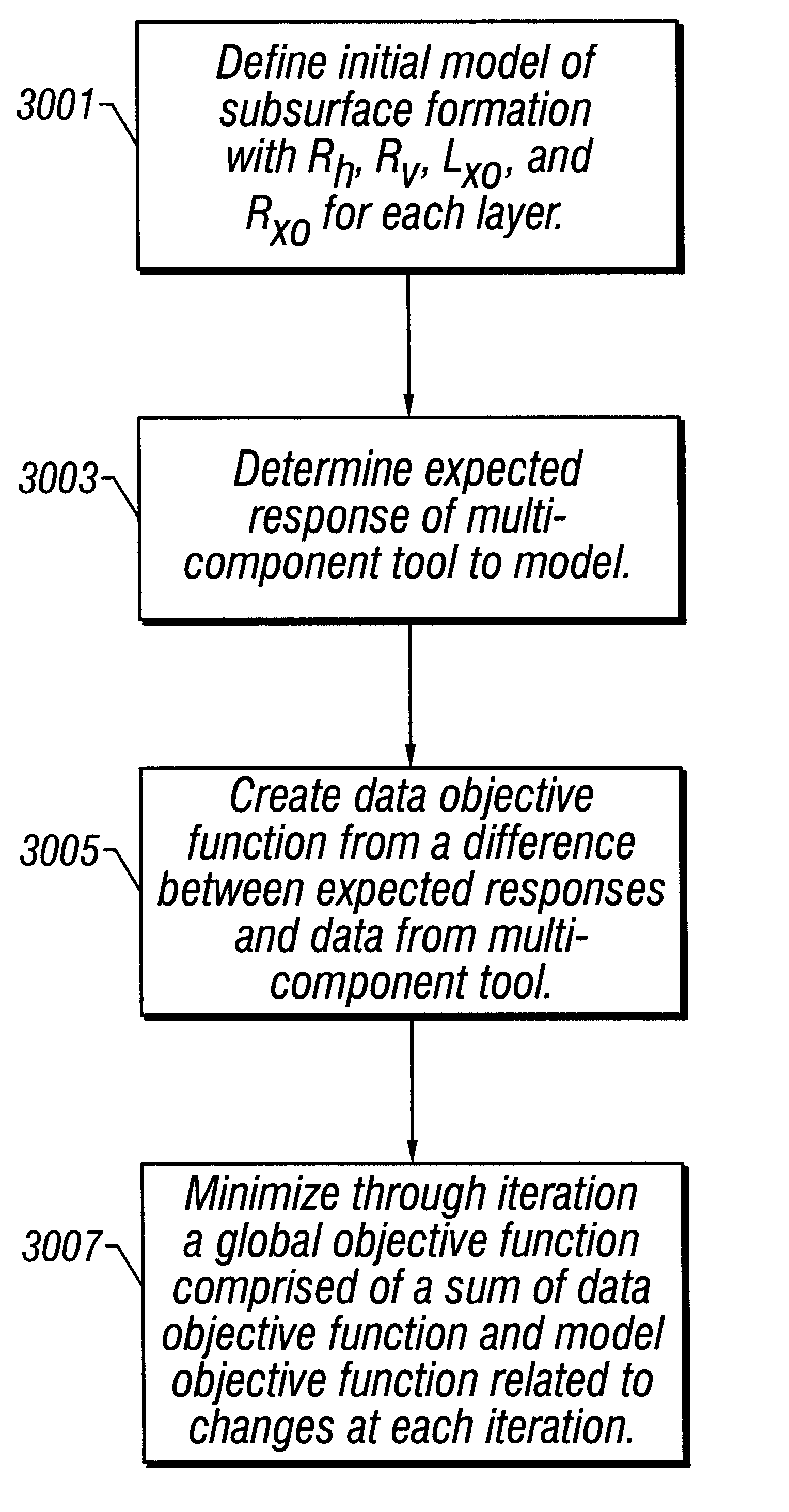
The most challenging part of the 2-D inversion is the appropriate handling of model parameters that have different physical units and different effects on the data.
This limitation becomes important only when constrained by availability of memory and processing capability.

Method used


Image

  • 2-D inversion of multi-component induction logging data to resolve anisotropic resistivity structure
  • 2-D inversion of multi-component induction logging data to resolve anisotropic resistivity structure
  • 2-D inversion of multi-component induction logging data to resolve anisotropic resistivity structure

Examples


Embodiment Construction

Turning now to FIG. 5, the results of using the method of the present invention are shown. The shaded portion of left track 301 shows the model of the invasion zone that was used. The actual resistivity of the invasion zone is shown by the solid line in the track 311. The actual horizontal resistivity of the formation is shown by the solid line in track 321 while the solid line in track 331 shows the actual vertical resistivity of the layers.

Synthetic data were generated by forward modeling using the method given by Tamarchenko and Tabarovsky and 1% random Gaussian noise was added. Starting with an initial model in which the bed boundary locations are known and fixed, and with an initial isotropic model having a uniform resistivity of 1 .OMEGA.m for the formation and for the invaded zone, the data were first inverted using only the 3DEX.TM. data. The solid line in the track 301 is the inverted length of the invasion zone, the dashed line in track 311 is the inverted resistivity of t...


PUM


Abstract

High Definition Induction Logging (HDIL) tools provide reliable information about the vertical and radial variations of resistivity structure in isotropic media. Focusing techniques provide quantitative information about resistivity variation and qualitative information about invasion at the well site. Coaxial alignment of transmitter-receiver arrays with the borehole prevents obtaining information about anisotropy in vertical wells, thereby greatly limiting the application of array induction tools in the characterization of reservoirs with finely laminated sand / shale sequences. A multi-component induction tool, 3DEX(TM), enables the detection of anisotropy in laminated reservoirs. Multi-component data are invert to give an estimate of vertical and horizontal resistivity in a vertical borehole. 3DEX(TM) may encounter difficulties in looking through an invaded zone and detecting the anisotropy in the formations. Joint inversion of HDIL and 3DEX(TM) data enables identification of parameters of the invaded zone as well as of the anisotropic formations.

Description

1. Field of the InventionThe invention is related generally to the field of interpretation of measurements made by well logging instruments for the purpose of determining the properties of earth formations. More specifically, the invention is related to methods for 2-D inversion of induction logging data obtained with transverse induction logging tools.2. Background of the ArtElectromagnetic induction and wave propagation logging tools are commonly used for determination of electrical properties of formations surrounding a borehole. These logging tools give measurements of apparent resistivity (or conductivity) of the formation that, when properly interpreted, are diagnostic of the petrophysical properties of the formation and the fluids therein.The physical principles of electromagnetic induction resistivity well logging are described, for example, in, H. G. Doll, Introduction to Induction Logging and Application to Logging of Wells Drilled with Oil Based Mud, Journal of Petroleum ...

Claims


Application Information

Patent Timeline
Patent Type & Authority Patents(United States)
IPC IPC(8): G01V3/28G01V3/18
CPCG01V3/28
Inventor ZHANG, ZHIYIMEZZATESTA, ALBERTO
Owner BAKER HUGHES HLDG LLC
Why Eureka
Try Eureka