Spindle device and machine tool utilizing the same

a spindle and machine tool technology, applied in the direction of bearing cooling, program control, instruments, etc., can solve the problems of increasing system cost, affecting the precision of high speed rotation and high dynamic stiffness, and the value is incapable of detecting the machining status associated with the frequency of rotation of the main sha

Inactive Publication Date: 2003-01-21
NTN CORP
View PDF23 Cites 57 Cited by
  • Summary
  • Abstract
  • Description
  • Claims
  • Application Information

AI Technical Summary

Problems solved by technology

However, the system of inferring the load during the machining in reference to the motor output measured value as hereinabove described has a problem in that a measuring instrument designed exclusively for that purpose is required, resulting in increase of the system cost.
Also, the system of detecting the machining status in reference to the motor output measured value is incapable of detecting the machining status associated with the frequency of rotation of the main shaft.
However, mere support of the main shaft solely by means of the magnetic bearings makes it difficult to secure a high precision of high speed rotation and a high dynamic stiffness.
However, to detect the machining status with respect to a number of frequency regions requires the use of an increased number of frequency filters, resulting in complicated structure and increase of the cost.
The spindle device with the externally pressurized gas bearing has a rotational precision generally in the order of 1 / 100.mu.m and is therefore suited for the highly precise machining, but has a problem in that the static stiffness and the load bearing capacity are small.
On the other hand, the spindle device with the magnetic bearing is excellent in terms of dynamic stiffness and load bearing capacity, but has a low accuracy of rotation of the main shaft.
However, the combined externally pressurized gas-magnetic bearing assembly has characteristics peculiar to the externally pressurized gas bearing and those peculiar to the magnetic bearing and, where the sensor for the magnetic bearing has a low resolution, since the rotational precision of the main shaft depends on this resolution, a high rotational precision exhibited by the externally pressurized gas bearing cannot be effectively utilized.
Also, although the combined externally pressurized gas-magnetic bearing assembly of the type discussed above is a non-contact bearing, there is the possibility that the main shaft may contact a bearing surface in the event that an excessive load acts.
However, since the combined externally pressurized gas-magnetic bearing assembly is of a design wherein the externally pressurized gas bearing is formed in the magnetic bearing unit, the gap between the main shaft in the bearing unit and a magnetic bearing stator is so small, for example, not greater than some tens microns and, therefore, the protective bearing in the form of the rolling bearing generally used in the spindle device with the magnetic bearing cannot be used.
Also, since the externally pressurized gas bearing surface forms a part of an electromagnet for the magnetic bearing, material for the externally pressurized gas bearing surface is limited to a ferromagnetic substance having no lubricating capability.
For this reason, in the event that an excessive load is applied to the spindle device, contact between the main shaft and the bearing surface brings about a detrimental influence on the bearing unit.
For this reason, it has been difficult to achieve a highly precise machining.
Accordingly, where the sensor for the magnetic bearing has a low resolution, the rotational precision of the main shaft depends on this resolution and, therefore, the high rotational precision generally exhibited by the externally pressurized gas bearing cannot be effectively utilized.
The load acting on the machining tool is represented by a vibration of the machining tool in view of the natural vibration of the machining tool, a work and the machine tool or the number of revolution of the main shaft, and the machining status such as damage to the machining tool gives rise to a peculiar tendency in the frequency of vibration depending on the type of machining defects.
However, since the main shaft (4) is driven at a high speed, it is difficult to achieve the temperature measurement.

Method used


Image

  • Spindle device and machine tool utilizing the same
  • Spindle device and machine tool utilizing the same
  • Spindle device and machine tool utilizing the same

Examples


second embodiment

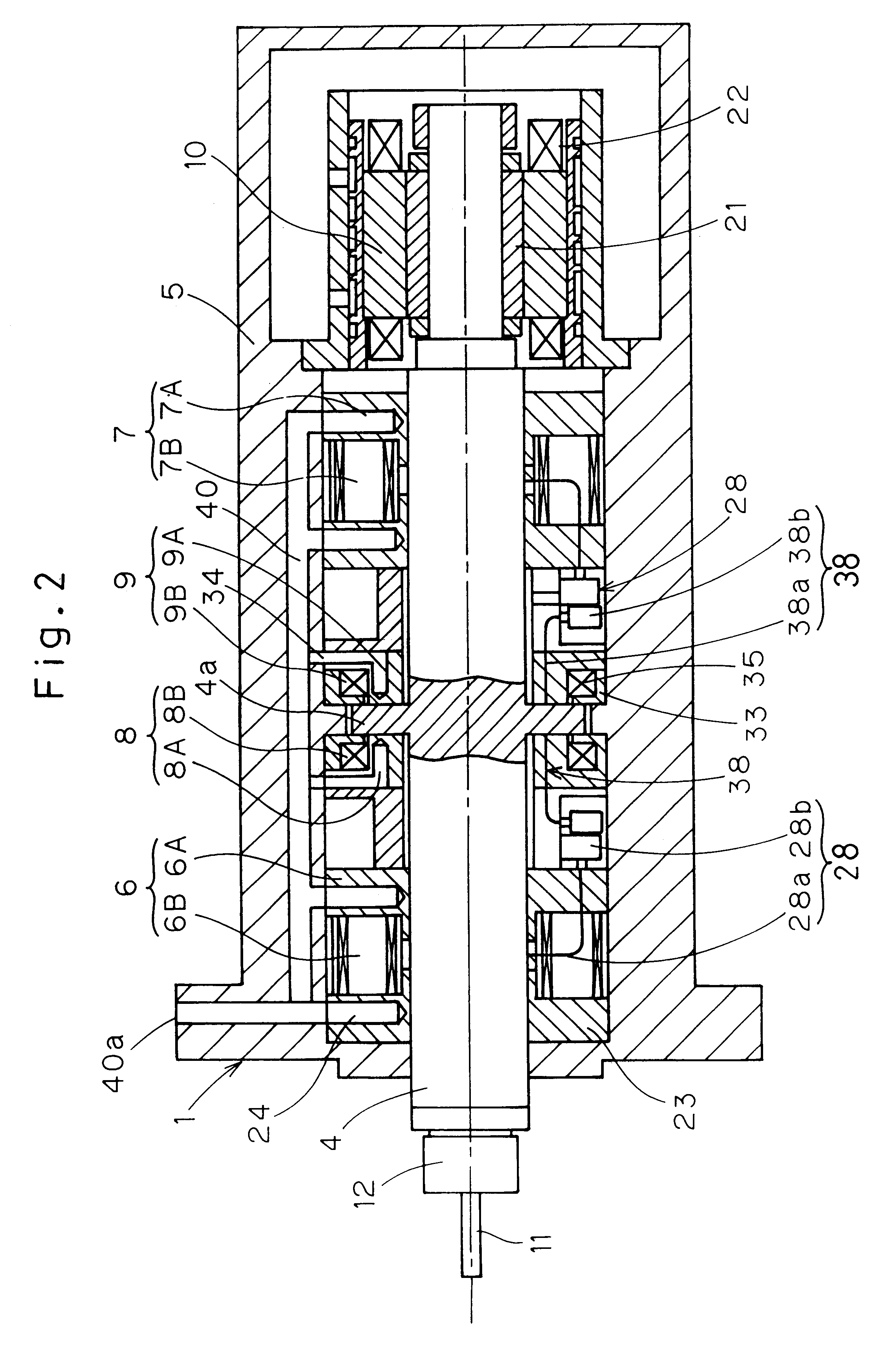
In the second embodiment shown in FIGS. 19 and 20, a slide member 47 having an inner peripheral surface positioned adjacent the main shaft 4 through a radial gap is disposed within the housing 5. This slide member 47 is disposed adjacent each of front and rear ends of the main shaft 4 with the combined externally pressurized gas-magnetic radial bearing assemblies 6 and 7 intervening therebetween. Each of the slide members 47 is in the form of a ring member and is mounted in a slide member mount formed within the housing 5. Each of the slide members 47 has an inner peripheral surface 47a of a cylindrical shape that cooperates with the outer peripheral surface of the main shaft 4 to define a radial gap d3 as shown in FIG. 20. This radial gap d3 is of a size smaller than the bearing gap d1 between the outer peripheral surface of the main shaft 4 and any of the externally pressurized gas bearings 6A or 7A and the magnetic bearings 6B or 7B both forming respective parts of the combined e...

third embodiment

While the specific structure of each of the combined externally pressurized gas-magnetic bearing assemblies 6 to 9 employed in the practice of the third embodiment differs from those employed in the foregoing embodiment shown in FIG. 19, any of the combined externally pressurized gas-magnetic bearing assemblies 6 to 9 in FIGS. 19 and 20 is of a design in which the externally pressurized gas bearings 6A to 9A and the magnetic bearings 6B to 9B are combined together and, at the same time, the electromagnet cores 23 and 33 of the magnetic bearings 6B to 9B are utilized to form respective parts of the externally pressurized gas bearing surfaces.

In any event, even in the embodiment shown in FIG. 21, the relationship between the radial gaps, defined by the slide members 47, and the radial gaps defined by the combined externally pressurized gas-magnetic radial bearing assemblies 6 and 7 and the type of material for the slide members 47 remain the same as those discussed in connection with ...

first embodiment

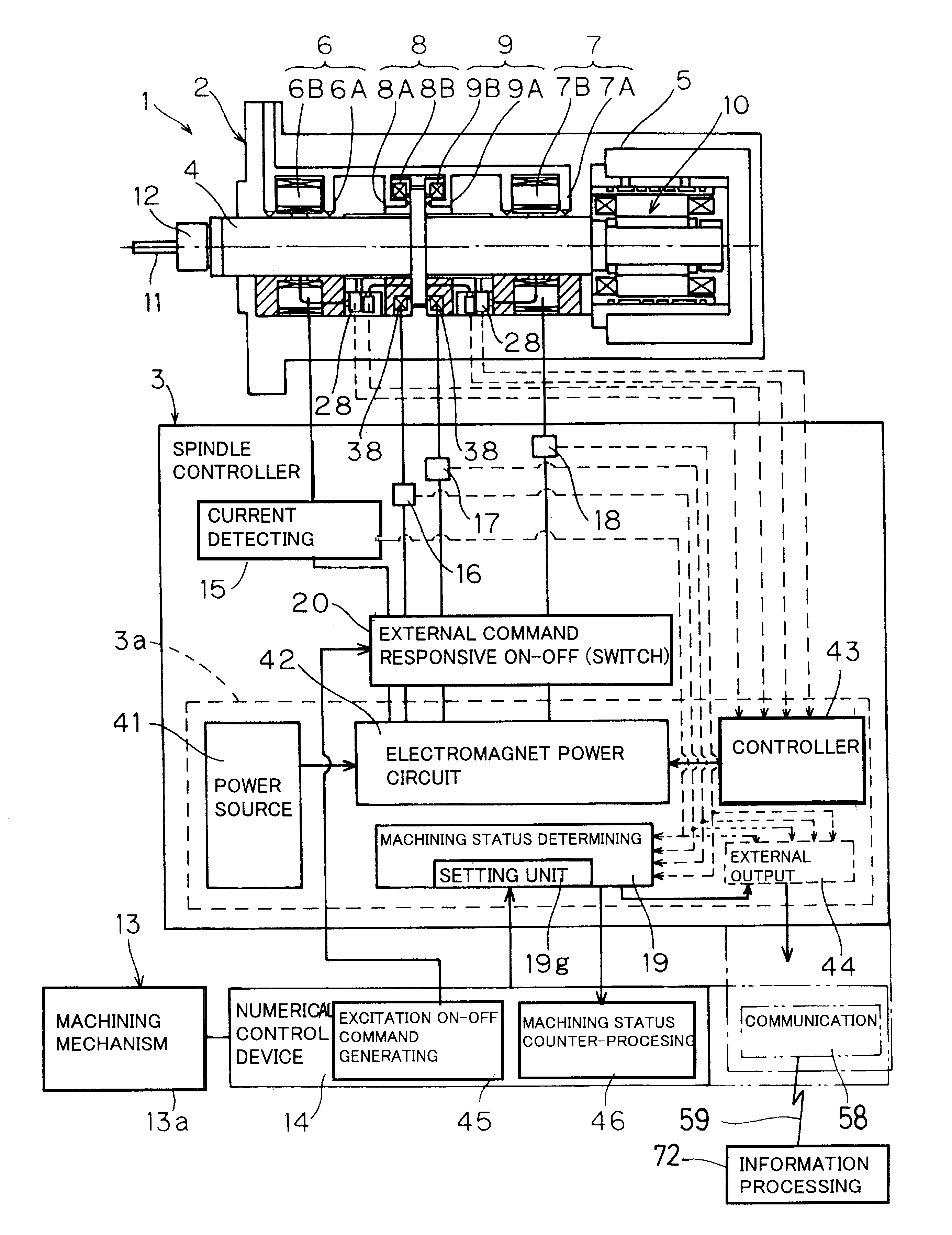
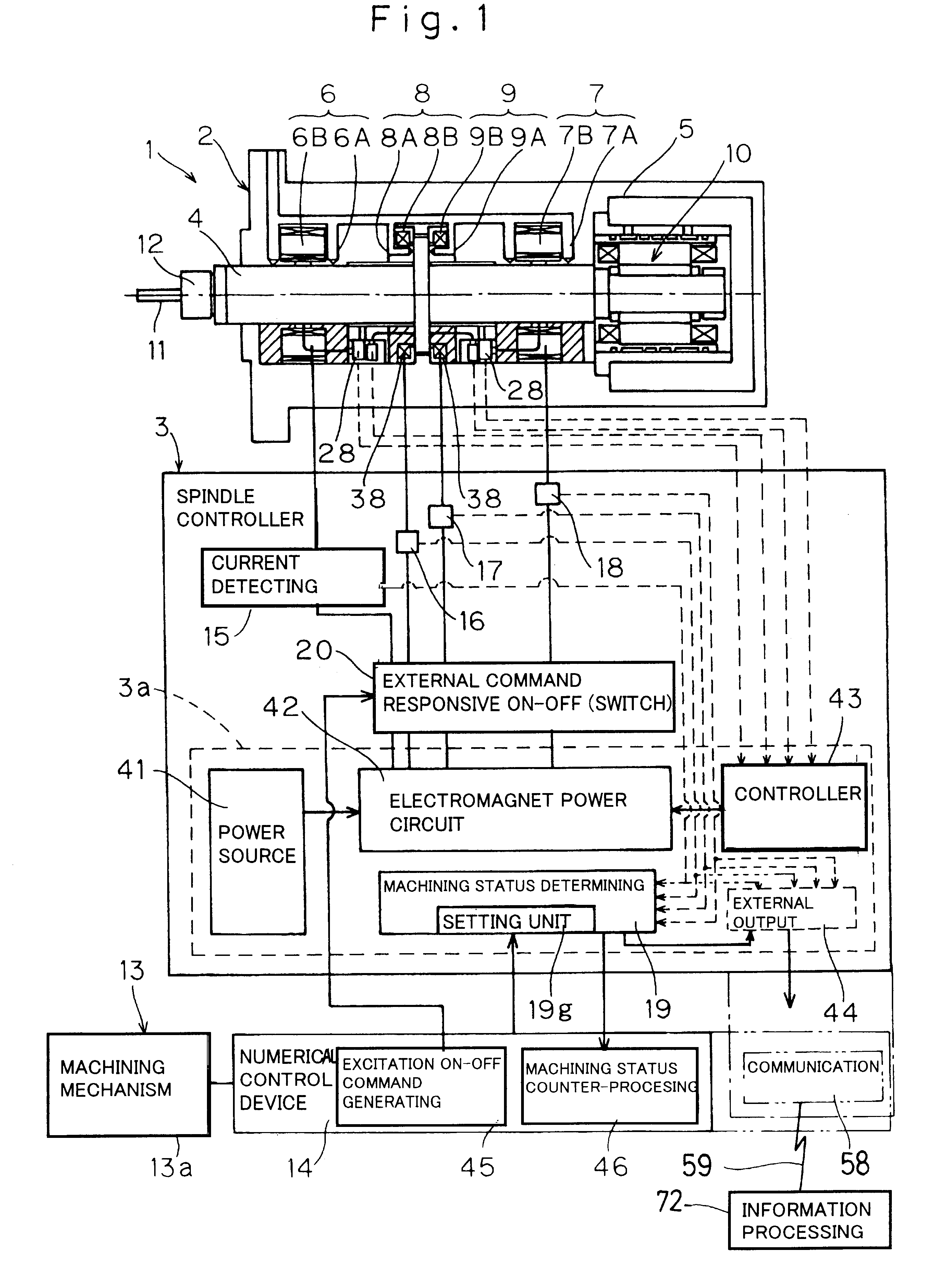
The spindle device 1C equipped with the combined externally pressurized gas-magnetic bearing assemblies according to a fourth preferred embodiment of the present invention is shown in FIG. 22. Even in the embodiment shown in FIG. 22, component parts of the spindle device 1C that are alike those employed in the spindle device 1 of the first embodiment shown particularly in FIG. 1 are shown by like reference numerals.

In the spindle device 1C shown therein, a cooling means 73 is utilized, which includes a coolant flow passage 74 such as, for example, a water jacket provided in the housing 5, and a cooling unit 75 for circulating a cooling medium such as, for example, a cooling water through the coolant flow passage 74.

This spindle device 1C is incorporated in the machining apparatus 13 such as, for example, a high speed milling machine or a high speed grinding machine and the machining mechanism 13a of the machining apparatus 13 is controlled by the numerical control device 14. The hou...


PUM

PropertyMeasurementUnit
Shore hardnessaaaaaaaaaa
currentaaaaaaaaaa

Abstract

A spindle device equipped with a combined externally pressurized gas-magnetic bearing assembly, and a machining apparatus utilizing the spindle device. The spindle device is capable of accomplishing a high speed rotation with high rotational precision and includes a main shaft (4) rotatably supported by the combined bearing assembly (6 to 9), an electric current detecting device (15 to 18) disposed in a spindle controller (3) for detecting a current supplied to electromagnets of the combined bearing assembly (6 to 9). Also provided is a machining status determining device (19) for determining the machining status in reference to the current detected by the current detecting device (15 to 18). The machining status may be an indication of the extent to which a machining tool is impaired.

Description

1. Field of the InventionThe present invention relates to a spindle device and, more particularly, to the spindle device provided with externally pressurized gas bearings or combined externally pressurized gas-magnetic bearings and also to a machining apparatus equipped with the same.2. Description of the Prior ArtIn recent years, a highly efficient, highly precise machining has drawn keen attentions in the field of a mold machining field. In order to implement such a machining, it is necessary to use a spindle device capable of accomplish a high speed rotation with high rotational precision and having a static stiffness and a dynamic stiffness, and it is also required to perform the machining under optimum machining conditions by detecting the status of machining.To meet these requirements, the applicant has suggested a hybrid type non-contact bearing assembly in which externally pressurized gas bearings and magnetic bearings are combined together as disclosed in the Japanese Laid-...

Claims


Application Information

Patent Timeline
Patent Type & Authority Patents(United States)
IPC IPC(8): B23Q15/18B23Q15/16B23Q1/70B23Q1/52B23Q15/007B23Q17/09B23Q1/26B23Q1/38B23Q1/25B23Q1/00F16C39/06
CPCB23Q1/38B23Q1/70B23Q15/16B23Q15/18B23Q17/09F16C32/0402F16C32/0603F16C37/00F16C32/0489B23Q1/52Y10T409/306832F16C2322/39G05B2219/21031G05B2219/37285G05B2219/42328G05B2219/49209G05B2219/49271Y10T409/309352Y10T409/303976Y10T409/307224B23Q17/0957
Inventor OZAKI, TAKAYOSHISUZUKI, NOBUYUKI
Owner NTN CORP
Why Eureka
Try Eureka