Cable and line inspection mechanism

a technology of cable and line, applied in the field of automatic mechanisms, can solve problems such as bird caging, failure of cable, frayed or jammed strands,

Inactive Publication Date: 2003-01-28
NASA
View PDF21 Cites 35 Cited by
  • Summary
  • Abstract
  • Description
  • Claims
  • Application Information

AI Technical Summary

Benefits of technology

The mirror assembly includes first and second mirrors that are positioned facing portions of the cable that are facing away from the camera lens so that three parallel images of the cable are simultaneously supplied to the camera lens, each of which is of a different section of the cable. This enables the entire circumference of the cable to be imaged without rotational scanning of the camera around the cable.
Other sensing devices are also employed in the preferred embodiment. These include a laser micrometer that measures the diameter of the cable so that...

Problems solved by technology

Cable failures are characterized by frayed or jammed strands, bird caging, stretching and corrosion.
However, human application of tactile and visual senses in this...

Method used


Image

  • Cable and line inspection mechanism
  • Cable and line inspection mechanism
  • Cable and line inspection mechanism

Examples


Embodiment Construction

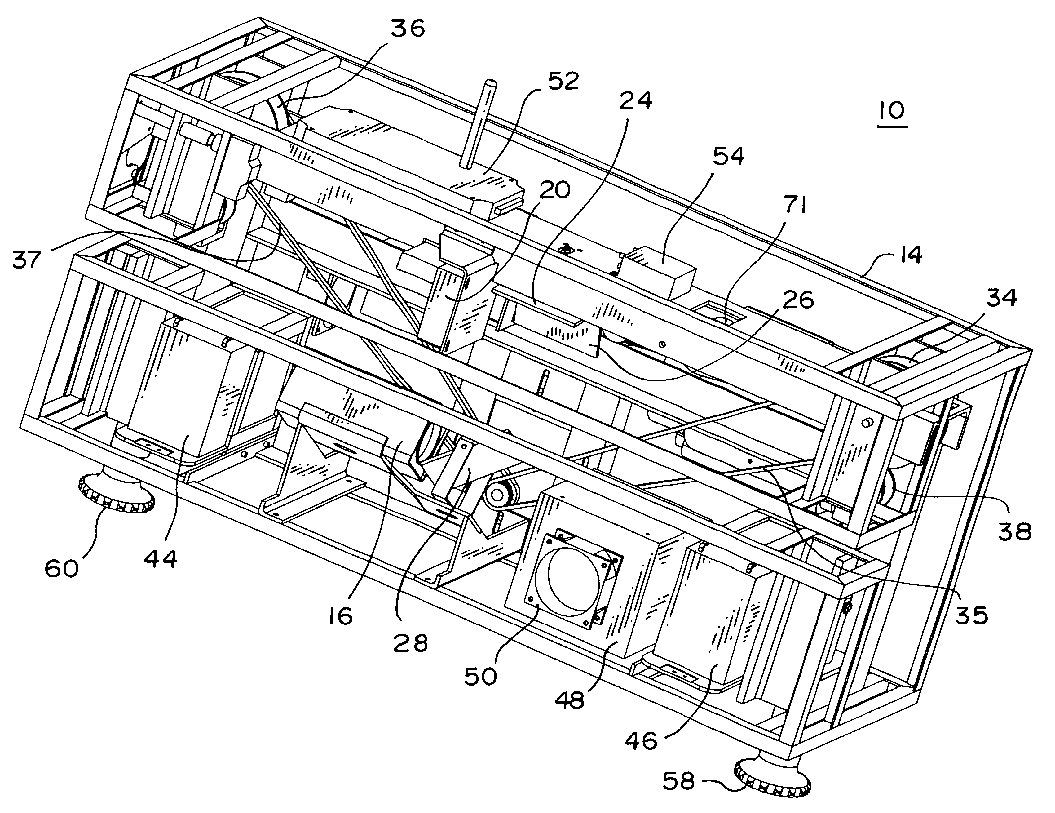
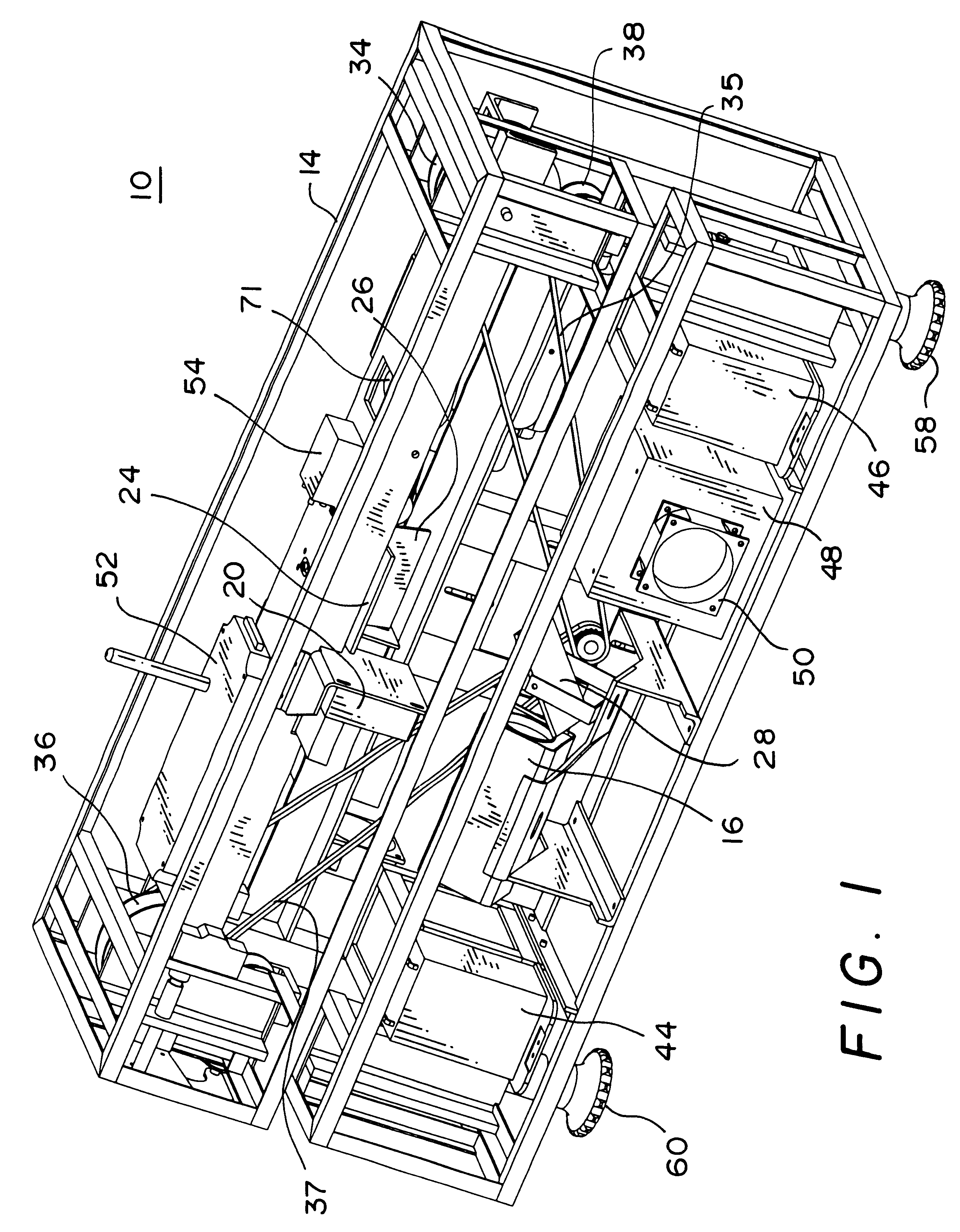
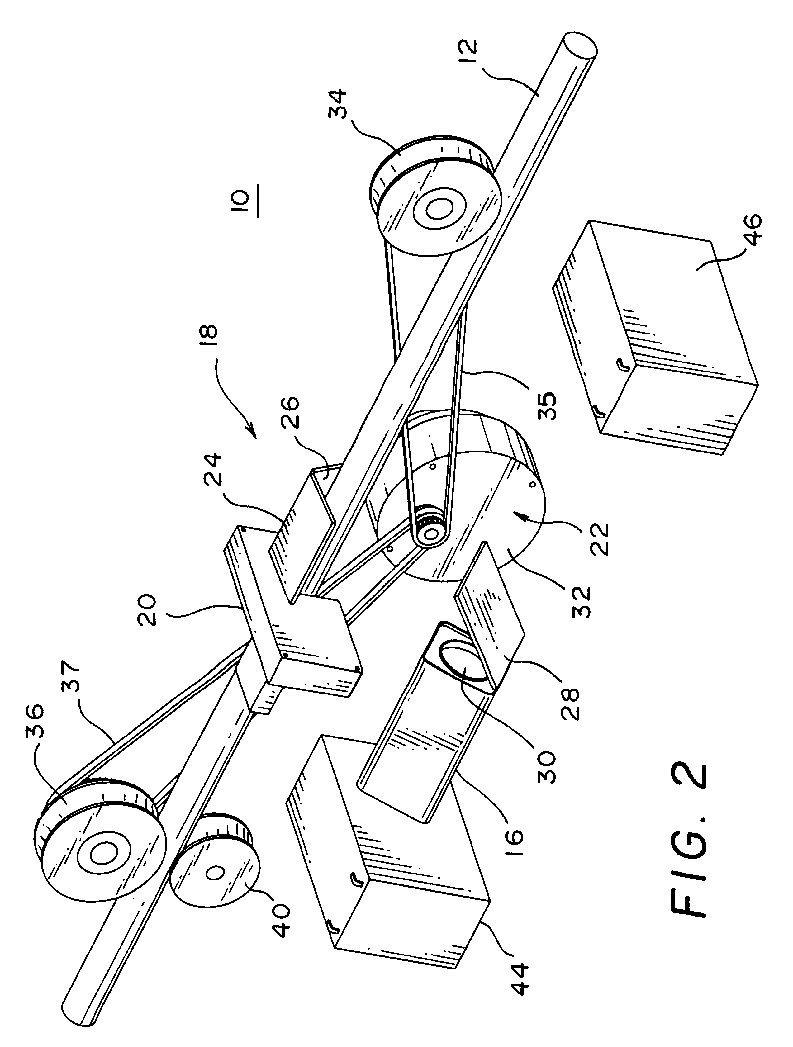
With reference to FIGS. 1-5, a cable and line inspection mechanism (CLIM) 10 is illustrated for visually inspecting a cable or line 12 (see FIG. 2) in accordance with a preferred embodiment of the present invention. The CLIM 10 includes a frame 14, to which are mounted, a number of elements. As best illustrated in the schematic illustration of FIG. 2, several of the key elements include a video camera 16, a mirror assembly 18, a laser micrometer 20 for measuring the diameter of the cable 12, and a drive system 22.

The mirror assembly 18 includes first and second mirrors 24 and 26 that are positioned adjacent to, and at an angle to, one another. A third mirror 28 is disposed adjacent a lens 30 of the video camera 16 at an angle thereto so that the camera 16 can be positioned parallel to a longitudinal axis of the cable 12 for packaging efficiency. It will be understood, however, that the third mirror could be left out if the camera 16 were positioned perpendicular to the cable 12. The...


PUM


Abstract

An automated cable and line inspection mechanism visually scans the entire surface of a cable as the mechanism travels along the cable=s length. The mechanism includes a drive system, a video camera, a mirror assembly for providing the camera with a 360 degree view of the cable, and a laser micrometer for measuring the cable=s diameter. The drive system includes an electric motor and a plurality of drive wheels and tension wheels for engaging the cable or line to be inspected, and driving the mechanism along the cable. The mirror assembly includes mirrors that are positioned to project multiple images of the cable on the camera lens, each of which is of a different portion of the cable. A data transceiver and a video transmitter are preferably employed for transmission of video images, data and commands between the mechanism and a remote control station.

Description

BACKGROUND OF THE INVENTIONThe present invention relates in general to an automated mechanism for optically inspecting cables, lines and the like.The launch pads at Kennedy Space Center employ emergency egress systems in which slidewire cables and baskets are utilized to permit astronauts to descend quickly and safely away from the launch vehicle in case of an emergency. Periodic inspections of the cables are necessary to insure that failures have not occurred which could jeopardize safety. Cable failures are characterized by frayed or jammed strands, bird caging, stretching and corrosion. Inspection crews have been employed in the past to inspect the cables visually as they are lowered down the cables at a controlled speed in a slidewire basket. However, human application of tactile and visual senses in this manner limits the data obtained during the inspections to pass or fail indications. In addition, this operation is obviously hazardous, man intensive and time consuming. An alt...

Claims


Application Information

Patent Timeline
IPC IPC(8): G01B11/10G01B11/08G01N21/952G01N21/88H04N7/18
CPCG01B11/105H04N7/185G01N21/952
Inventor ROSS, TERENCE J.
Owner NASA
Why Eureka
Try Eureka