

Method of making a spray formed rapid tool
a technology of rapid toolmaking and spray molding, which is applied in the direction of manufacturing tools, foundry patterns, moulding apparatus, etc., can solve the problems of time-consuming and labor-intensive steps, and the need for heat treatment to make the spray formed rapid tool
- Summary
- Abstract
- Description
- Claims
- Application Information
AI Technical Summary
Problems solved by technology
Method used
Image

Examples
Embodiment Construction
)
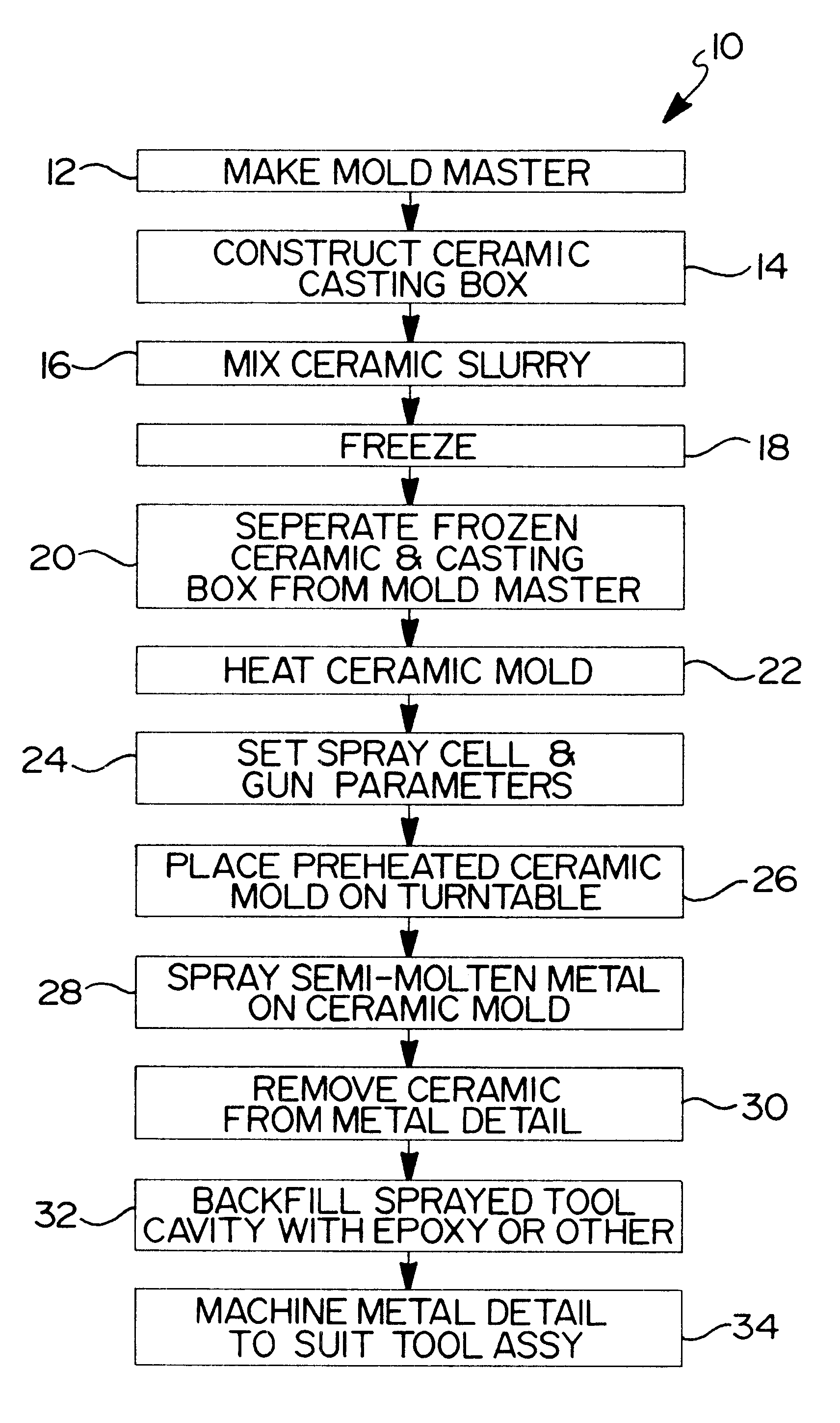
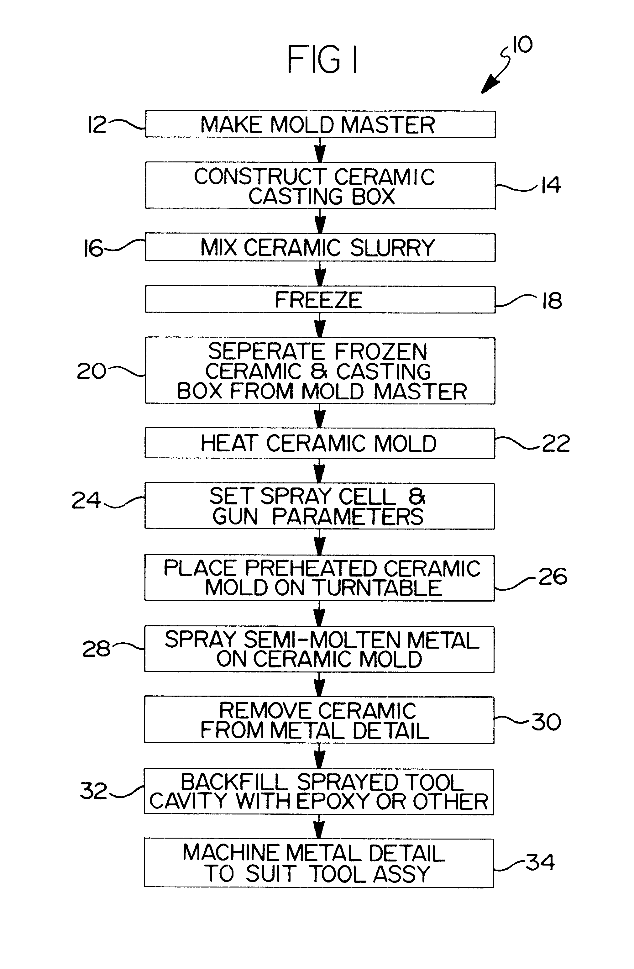
Referring to the drawings and in particular FIG. 1, one embodiment of a method, according to the present invention, of making a spray formed rapid tool is shown at 10. The method begins in block 12 and includes the step of creating or making a master model of a desired tool. Typically, the master model may be produced by using a CAD / CAM design and a free-form fabrication system such as stereo lithography. Such a process is disclosed in U.S. Pat. No. 5,658,506 to White et al., the disclosure of which is hereby incorporated by reference. It should be appreciated that the master model includes shrink factors, CNC machine references, and hand finishing.
After block 12, the method advances to block 14 and includes the step of constructing a ceramic casting box for the master model. To create the ceramic casting box, the bottom of the master model is adhered to a base plate (not shown) of an open box (not shown); the box is open at its top. It should be appreciated that brass pushoffs may...
PUM
| Property | Measurement | Unit |
|---|---|---|
| thickness | aaaaa | aaaaa |
| shrinkage | aaaaa | aaaaa |
| compressive strengths | aaaaa | aaaaa |
Abstract
Description
Claims
Application Information