Directional drilling system

Inactive Publication Date: 2003-02-11
KLEMM GUNTER W
View PDF17 Cites 16 Cited by
  • Summary
  • Abstract
  • Description
  • Claims
  • Application Information

AI Technical Summary

Problems solved by technology

Thus, it is not usually possible to apply rotational movements with the drill column to the drill head to increase drilling capacity.
Despite the wash fluid (also called a supporting fluid) in the pilot hole, there may be considerable friction on the drill column, in particular with lengthy drilling, such as with distances of more than 100 meters.
Therefore, a limited axial pressure may be applied to the drill head over the drill column.
Because of the limited axial pressure that may be transferred over the drill column, it may be possible to a limited extent to drill by breaking rocks, for example, by means of drill bits on the drill head that are in contact with the material to be removed with an axial pressure and remove this material because of movements of the drill head.
Thus, in producing pilot holes, it is may be difficult to penetrate through harder materials, such as for example, in areas of rock a

Method used


Image

  • Directional drilling system
  • Directional drilling system
  • Directional drilling system

Examples


Embodiment Construction

)

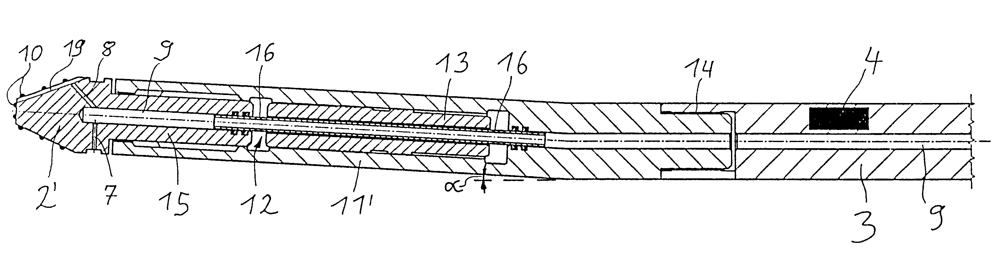
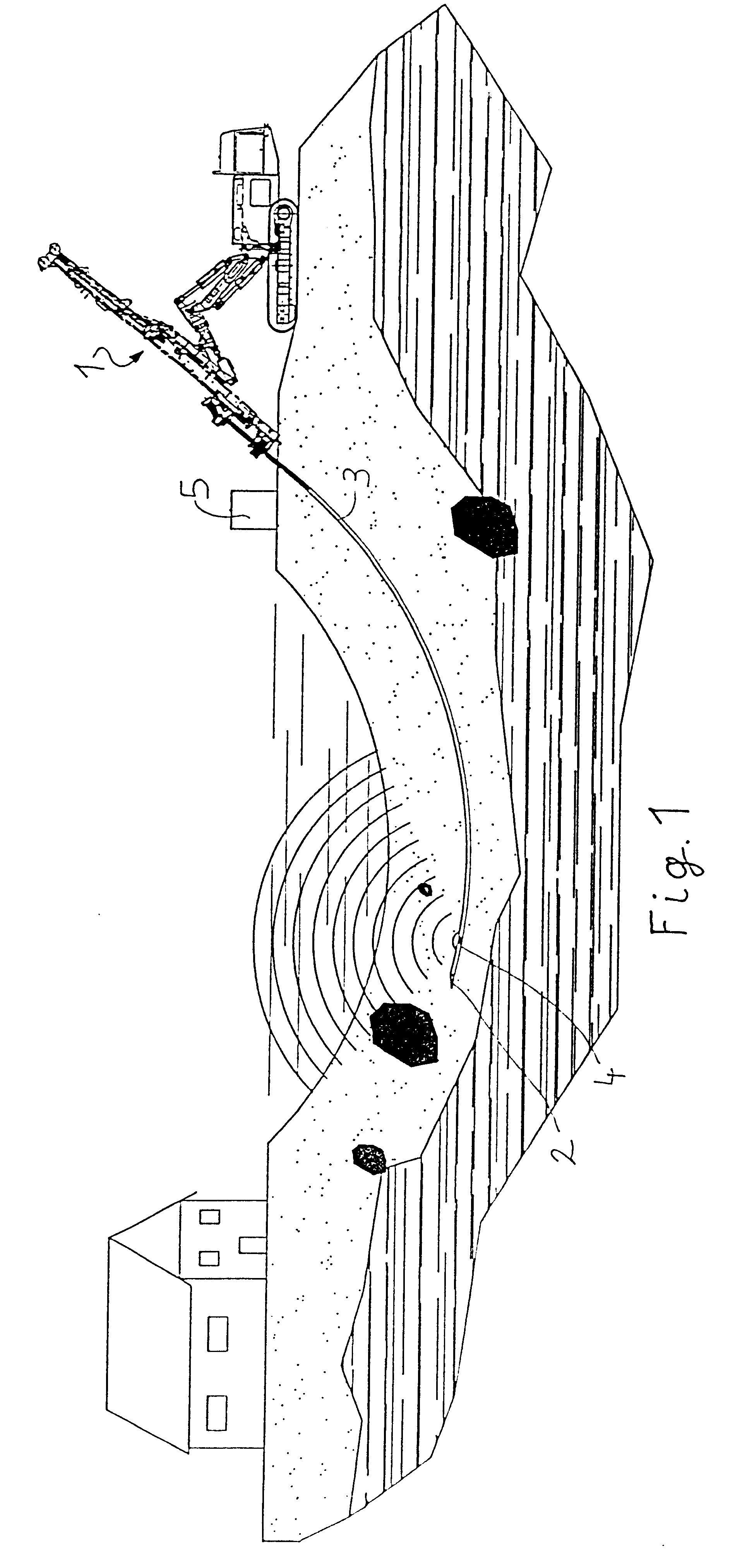
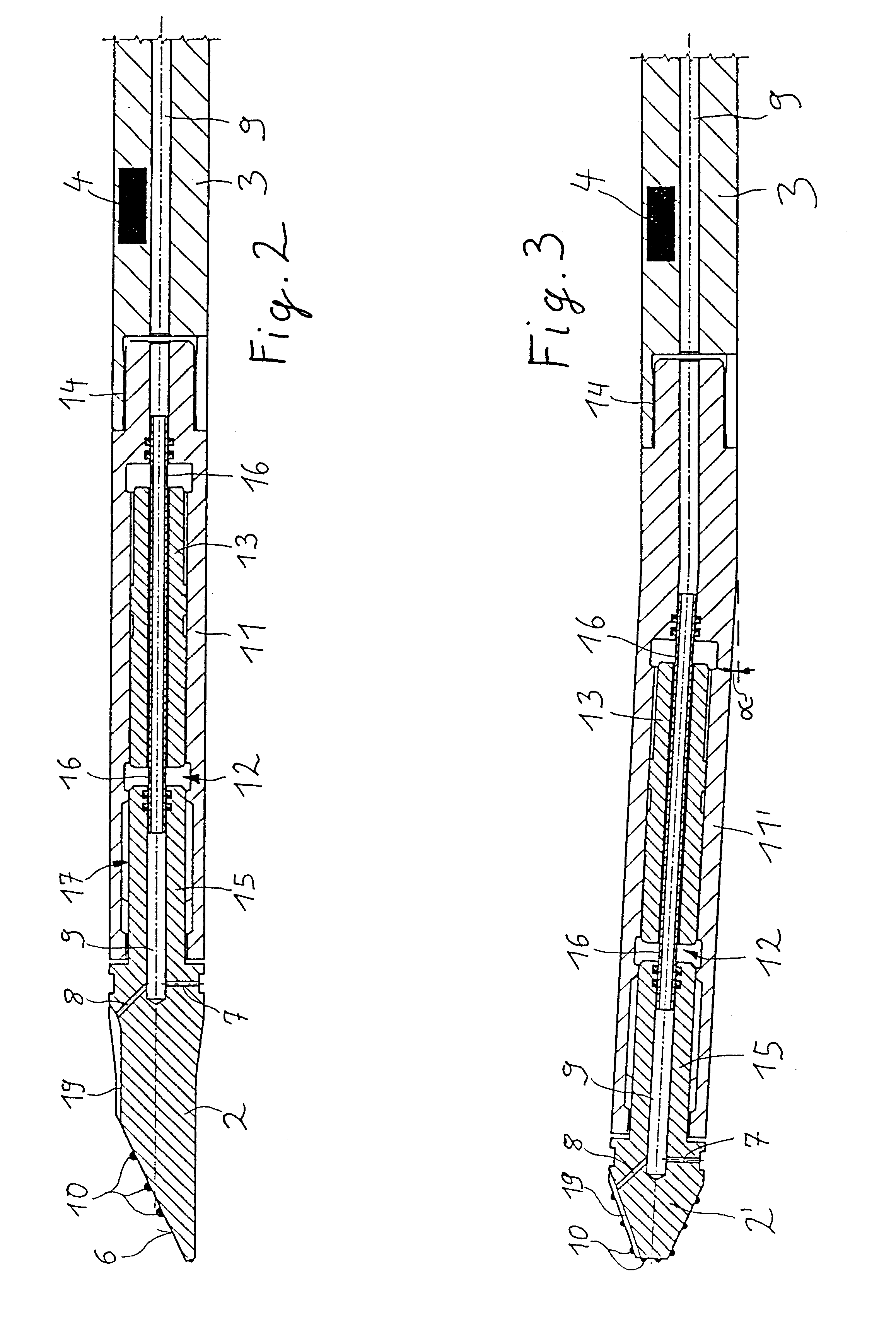
Referring to FIG. 1, shown is an example of a schematic diagram of a device for performing directional drilling. To produce a pilot hole, a drill head 2 is driven into the earth at an angle by a driving device 1 by means of a drill column 3. Near drill head 2 is arranged a probe 4. Probe 4 may be a magnetic probe which makes it possible to determine the precise position of drill head 2 by means of a navigation system and a monitoring unit. A driving device 1 may include a rotational device with which drill column 3 is driven to rotate about its longitudinal axis and may be locked in a certain angular position. In this way, the plane of the radius of curvature of the resulting drilling may be inclined in any desired direction. The drilling may thus be guided in any direction mostly parallel to the earth's surface. The drilling may in particular be guided from a point of entry into the earth to an exit opening with a large radius of curvature, as shown in FIG. 1, for example, so that...


PUM


Abstract

Disclosed is a device for directional drilling including a drill head mounted on a drill column. A driving device applies an axial driving force to the drill column. A delivery device supplies a wash medium to the drill head through a channel in the drill column. The device provides for increased removal of material and drilling through hard materials by by providing a housing on the drill head having a receptacle for an axially movable piston and a piston drive for producing strikes of the piston acting on the drill head. A connecting link permits an axial movement between the drill head and the drill column. A channel for the wash medium may be sealed at least with respect to the end faces of the piston.

Description

1. Field of the InventionThis application generally relates to drilling, and more particularly to a method and apparatus for directional drilling.2. Description of Related ArtFor many years, directional drilling has been a cost efficient and less complex alternative to traditional methods of laying pipelines and tubing in open construction. In directional drilling, a special drill head with a guidance piece is used to produce a pilot hole. The guidance piece may be formed either by an end face of the drill head inclined to the axial direction of the drill head or by a guide body bent at a small angle (less than 5.degree.) in the axial direction of the drill head behind the drill head. Due to the inclined face or the bend in the guide body, the drilling produced with this drill head runs along a circular line with a large radius of curvature. The order of magnitude of the radius of curvature may be, for example, more than 10 meters, or with long drillings, may be more than 100 meters...

Claims


Application Information

Patent Timeline
IPC IPC(8): E21B7/30E21B7/00E21B7/04E21B7/06E21B7/08
CPCE21B7/06E21B7/30E21B7/068E21B7/067
Inventor KLEMM, GUNTER W.
Owner KLEMM GUNTER W
Why Eureka
Try Eureka