Variable displacement pump including a control valve

a variable displacement pump and control valve technology, applied in the direction of machines/engines, positive displacement liquid engines, liquid fuel engines, etc., can solve the problems of auxiliary steering power loss, inability to maintain the necessary flow rate in the power steering system, and inability to achieve energy saving effects

Inactive Publication Date: 2003-02-25
HITACHI AUTOMOTIVE SYST STEERING
View PDF8 Cites 49 Cited by
  • Summary
  • Abstract
  • Description
  • Claims
  • Application Information

AI Technical Summary

Benefits of technology

Another object of the invention is to obtain a variable displacement pump which is an oil pressure pump for a vehicle power steering system and which provides a comfortable steering feeling by control corresponding to a travel condition such as speed of the vehicle, steering speed, etc. Further, the variable displacement pump can better show an energy saving effect by decreasing its discharge flow rate as soon as possible when steering is unnecessary such as when the vehicle travels straight. The discharge quantity of the pump is instantly increased to a necessary quantity when steering is requested, and designated auxiliary steering power is maintained.
That is, according to the invention, the spool of the control valve is positioned at a designated place in the axial direction by balancing a difference in upper and lower stream sides of the metering throttle, and discharge flow rate of pressure fluid from the pump chamber can be kept minimum. When axial thrust acts on the spool by the electronic driving unit, discharge flow rate of pressure fluid from the pump chamber can be increased to a desired value by connecting the pump suction side to the first fluid pressure chamber, for example, and by connecting fluid pressure of the lower stream side of the metering throttle to the second fluid pressure chamber.

Problems solved by technology

However, in the positive displacement pump having such a flow control valve, the load to the engine does not decrease even if a part of the pressure fluid is returned to a tank through the flow control valve, and an energy saving effect is not obtained because the horse power required to drive the pump is the same.
Therefore, the following disadvantageous conditions may arise.
During a steering operation at low speed travel, the necessary flow rate is not maintained in the power steering system because of the very small discharge of the pump.
Therefore, there is the possibility that auxiliary steering power will be lost.
Therefore, the conventional variable displacement pump has a limit on decreasing the discharge flow rate from the pump when the engine revolution cycle increases.
Therefore, a sufficient fluid supply and energy savings cannot be obtained.
For example, when the variable displacement pump is directly driven by the engine of the vehicle, a discharge quantity from the pump is unnecessary when there is no steering, even when the engine revolution cycle is large.

Method used


Image

  • Variable displacement pump including a control valve
  • Variable displacement pump including a control valve
  • Variable displacement pump including a control valve

Examples


Embodiment Construction

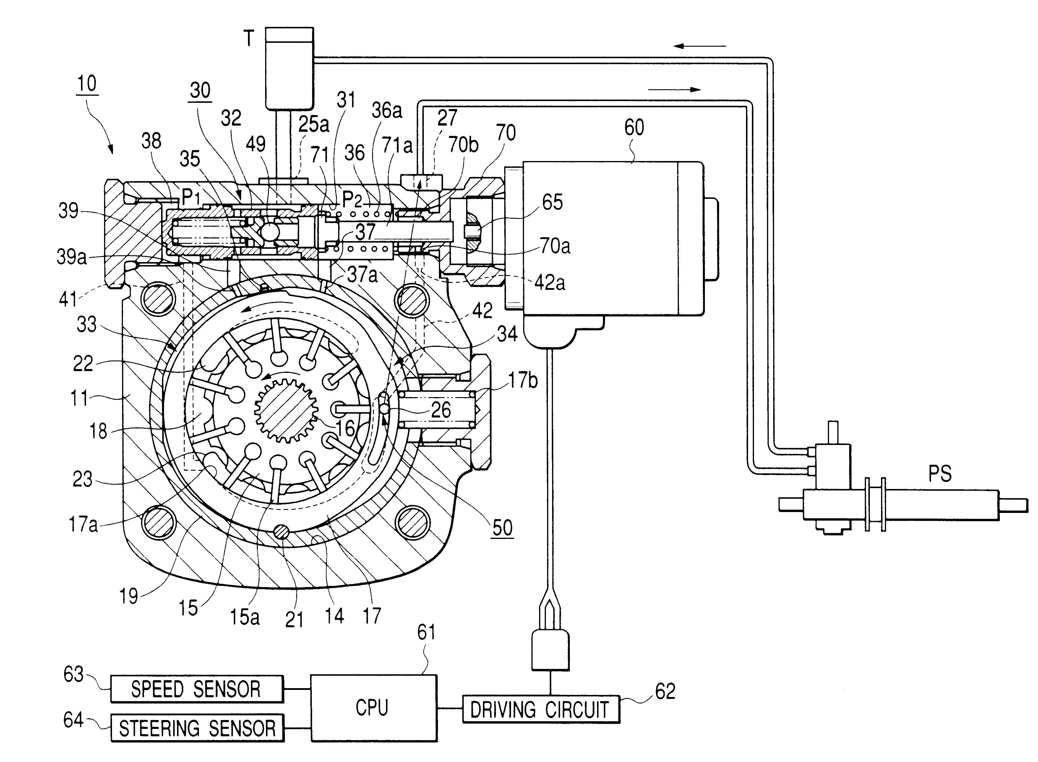
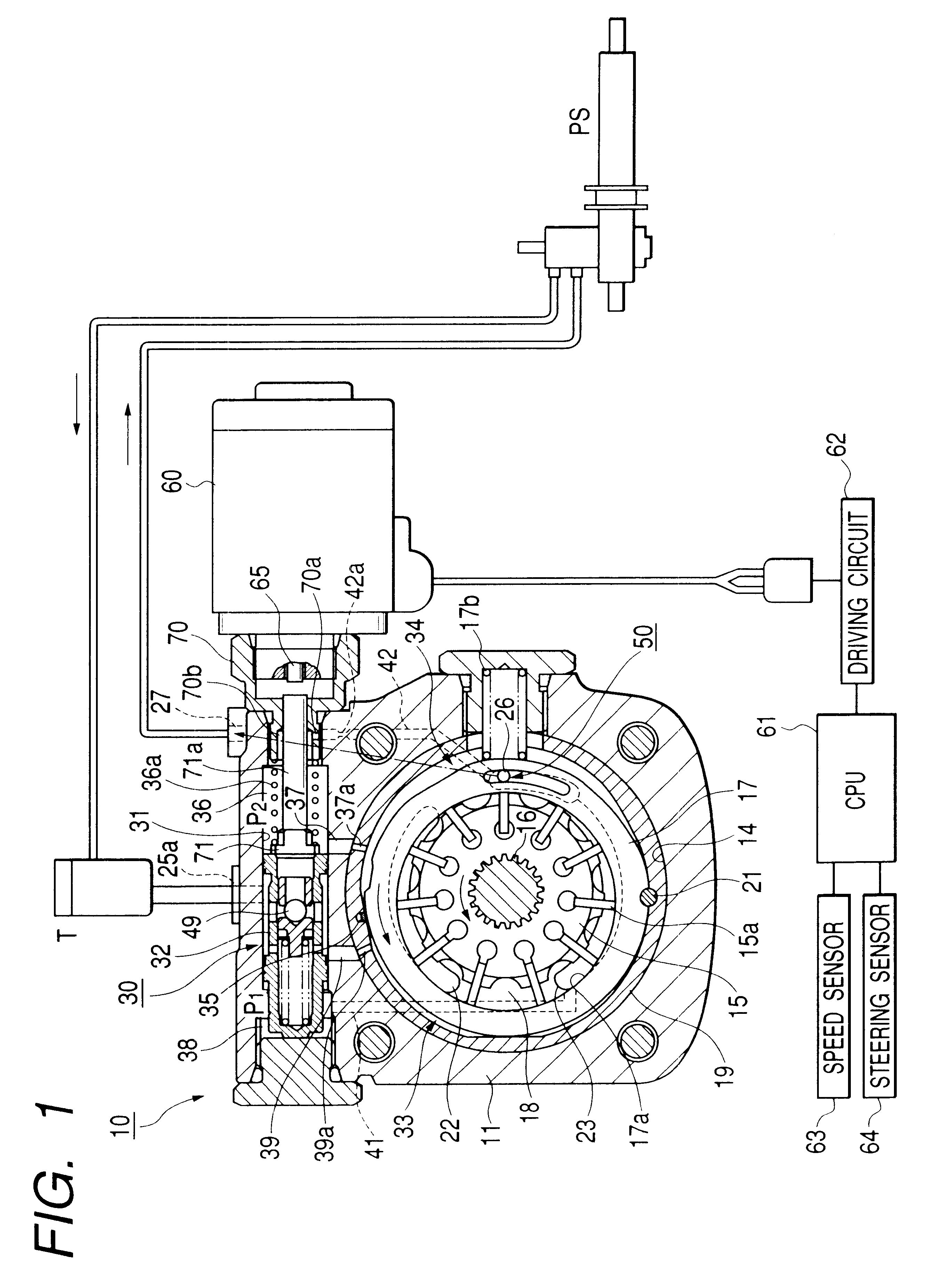
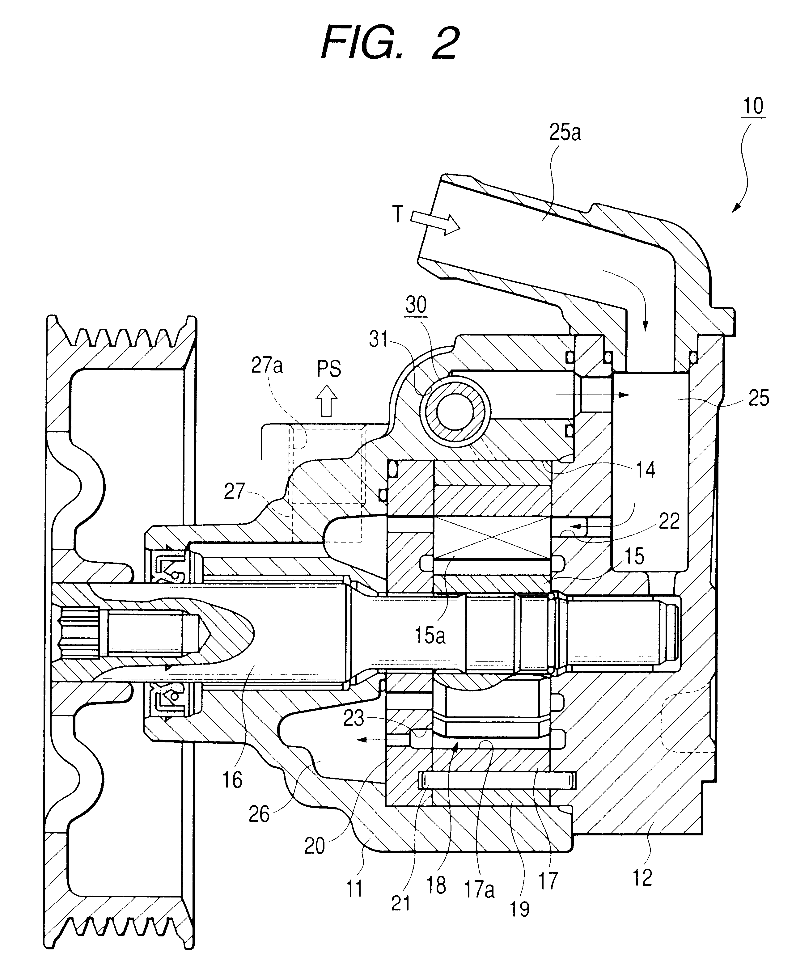
FIGS. 1 to 3 are views showing an embodiment of a variable displacement pump according to the invention. In the embodiment, it is described that the variable displacement pump according to the invention is used for a vane type oil pump that is an oil pressure generating source of a power steering system.

In FIG. 1 and FIG. 2, a vane-type variable displacement pump shown with symbol 10 has a front body 11 and a rear body 12 forming a pump body. The front body 11 has an overall cup shape. A storage space 14, for storing and arranging pump composing elements, is formed at the inside of the front body 11. The rear body 12 is attached to the front body 11 so as to block the open end of the storing space 14.

The front body 11 rotatably supports a driving shaft 16 that rotatingly drives a rotor 15, which together comprise pump composing elements. The drive shaft 16 penetrates through the front body. The rotor 15 rotates counterclockwise in FIG. 1.

Symbol 17 is a cam ring, the cam ring 17 has ...


PUM


Abstract

A pump including a pump chamber 18, formed in a pump body 11, between a cam ring 17 and a rotor 15. The cam ring is formed so as to move in a direction whereby the pump capacity of the pump chamber increases and decreases. First and second fluid pressure chambers 33 and 34 are formed at opposite sides of the cam ring 17. The pump has a spool that is axially moved by a difference in fluid pressure between upper and lower stream sides of a metering throttle 50 connected to a discharge side passage 27 of the pump chamber. The spool is part of a control valve 30 that controls fluid pressure in at least the first fluid pressure chamber. An electronic driving unit, for example, a solenoid 60, applies axial thrust to the spool of the control valve.

Description

1. Field of the InventionThe present invention relates to a variable displacement pump used as an oil or fluid pressure source for a vehicle power steering system, for example.2. Description of the Related ArtIn the pump for a power steering system, it is desired that fluid pressure--of an amount sufficient to obtain auxiliary steering power corresponding to a steering state during operation of a steering wheel--is applied to a power cylinder of a power steering system. On the other hand, it is unnecessary to apply such pressure when there is no steering, as when the vehicle travels straight.Moreover, in a power-steering-system pump, it is desired that supplying quantity of pressure fluid at high speed travel is less than at middle or low speed travel and travel stability at high speed straight travel is kept with rigid feeling of steering wheel at high speed travel.A positive displacement pump driven by an engine of vehicle is generally used as the pump for a power steering system....

Claims


Application Information

Patent Timeline
Patent Type & Authority Patents(United States)
IPC IPC(8): B62D5/07B62D6/00F04B49/00F04B1/06F04B1/00F04C14/00F04C14/22F04C14/24F04C15/06
CPCF04C14/226F04C2/344F04C14/10F04C15/06
Inventor KONISHI, HIDEO
Owner HITACHI AUTOMOTIVE SYST STEERING
Why Eureka
Try Eureka