
Apparatus and process for a cross-direction profile of a material web

Inactive Publication Date: 2003-02-25
VOITH SULZER PAPIERTECHN PATENT
View PDF33 Cites 21 Cited by
  • Summary
  • Abstract
  • Description
  • Claims
  • Application Information

AI Technical Summary

Benefits of technology

In particular, the present invention can be utilized to reduce control times. For example, it can be advantageous to position at least one stationary cross-direction profile measurement device immediately before and / or immediately after at least one actuator or control element, which is provided to control the respective cross-direction profile.
For example, in connection with a "speed coater," an underlying control circuit can keep the layer thickness constant on the application roll. A superimposed control circuit can take care of proper maintenance of, e.g., absolute values of the coating application.

Problems solved by technology

Among other disadvantages, the known measurement systems require measurements to be taken mainly in long, free stretches of the material web.
Measurement is normally possible only in the wire section and at the end of a respective paper machine, however, excessively long operating cycles tend to result due to the large number of final control elements lying between, which causes relatively imprecise control.
However, the expensive image processing is particularly disadvantageous.
While these measurement devices can be arranged relatively near the headbox control elements in question, a disadvantage is that conductivity is a measure of moisture and not of surface weight.
The longer service life of LEDs compared to lamps with filaments is critical because, for the application of the cross-direction profile measurement, between 50 and 500 sensors may be customarily used simultaneously, and it unreasonable for the operator be continually dealing with lamp failures.
Alternatively, or additionally,, a measurement in the transmitted light method is also possible, however, this may be associated with a higher cost of operation.

Method used


Image

  • Apparatus and process for a cross-direction profile of a material web
  • Apparatus and process for a cross-direction profile of a material web

Examples


Embodiment Construction

The particulars shown herein are by way of example and for purposes of illustrative discussion of the embodiments of the present invention only and are presented in the cause of providing what is believed to be the most useful and readily understood description of the principles and conceptual aspects of the present invention. In this regard, no attempt is made to show structural details of the present invention in more detail than is necessary for the fundamental understanding of the present invention, the description taken with the drawings making apparent to those skilled in the art how the several forms of the present invention may be embodied in practice.

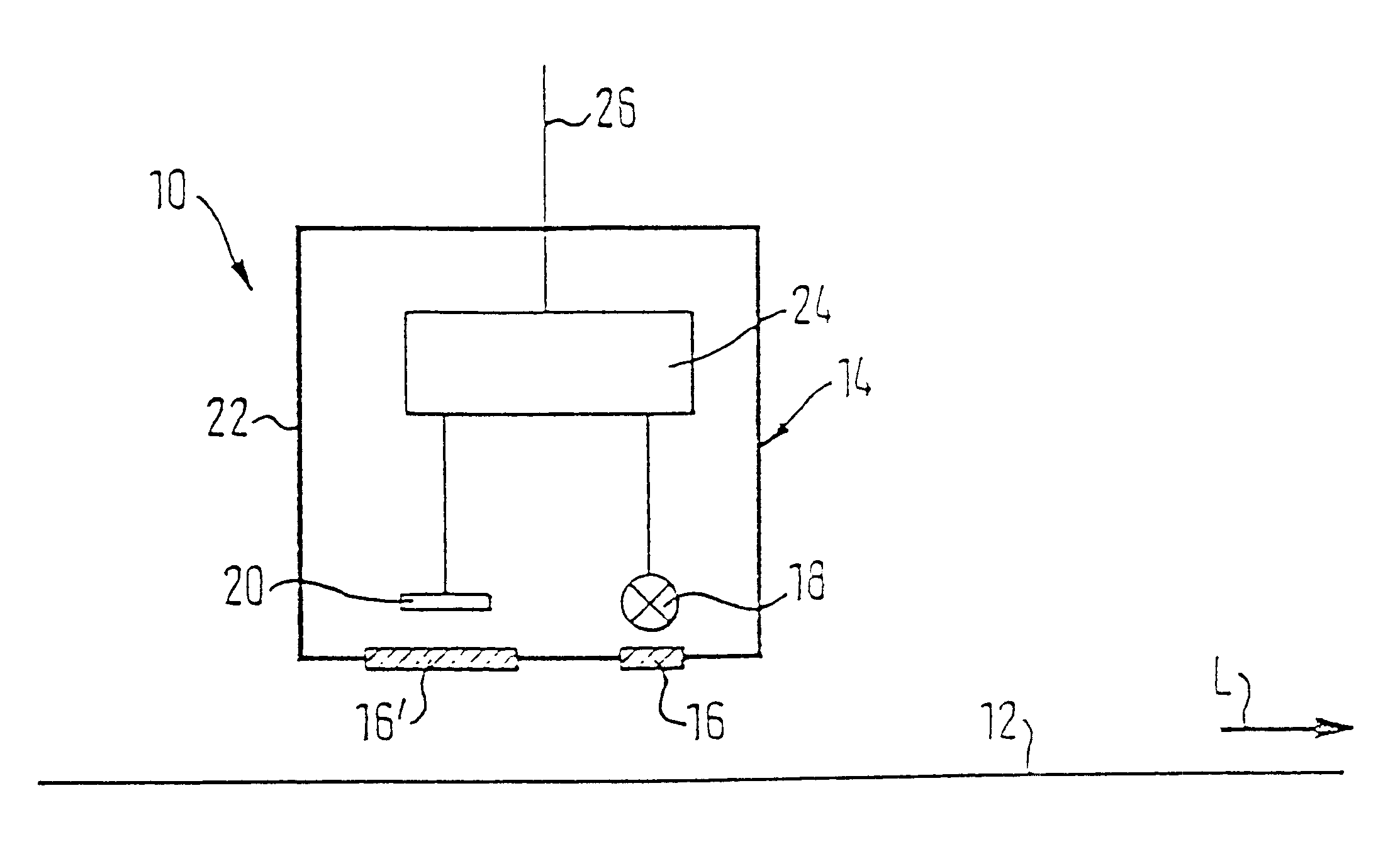
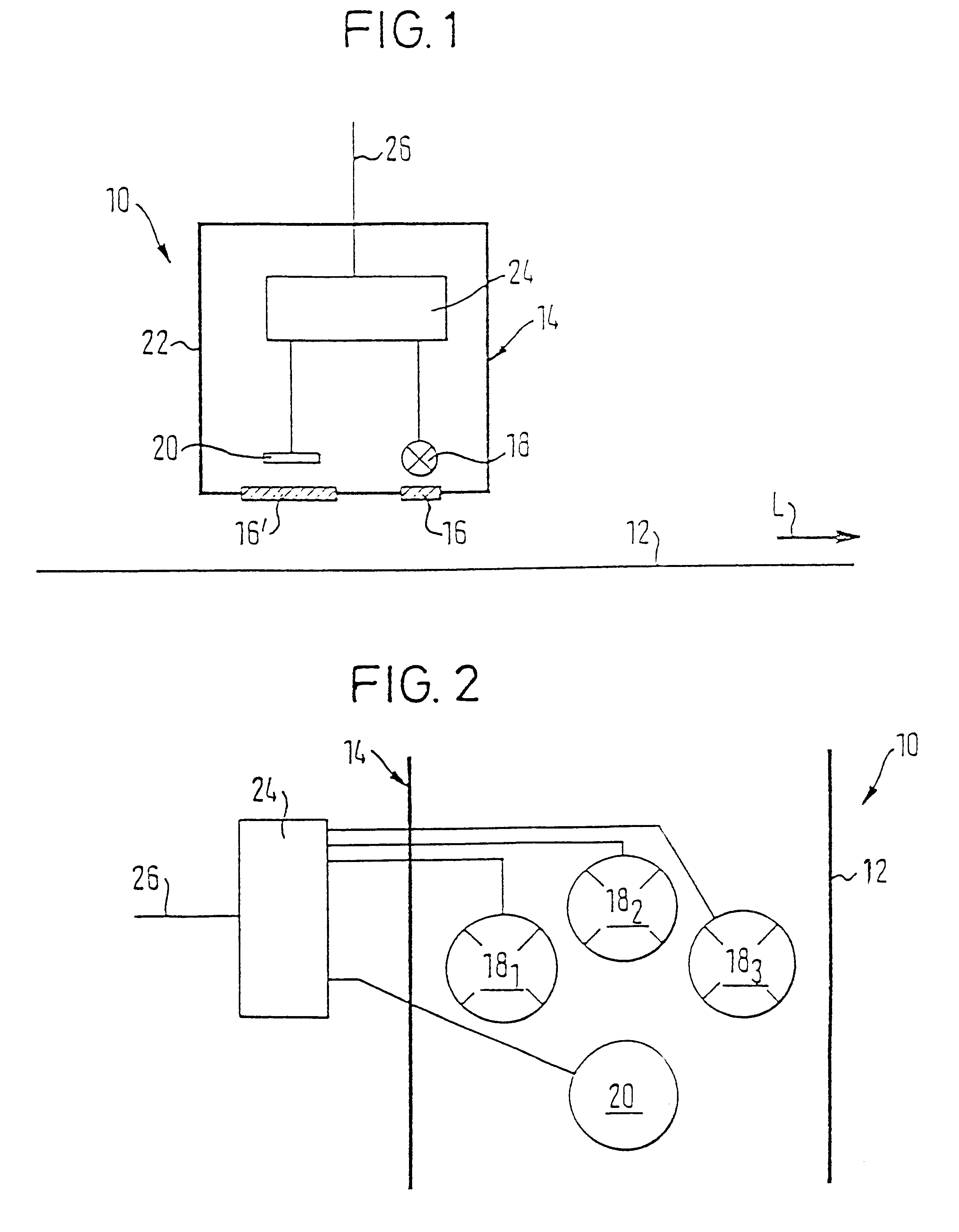
FIG. 1 schematically illustrates a measurement system 10 for measurement of the cross-direction profile of specific properties of a material web 12, e.g., a fibrous material web, in a paper and / or cardboard machine or a coating machine.

Measurement system 10 can include at least one stationary cross-direction profile measurement...


PUM


Abstract

Measurement system and process for measuring a cross-direction profile of specific properties of at least one of a material web and a coating on the material web. The system includes at least one stationary cross-direction profile measurement device having at least one radiation source adapted to irradiate the at least one of the material web and the coating on the material web in a plurality of defined and different wavelength ranges, and at least one sensor adapted to measure the intensity of radiation affected by the at least one of the material web and the coating on the material web. The system also includes at least one measurement and / or evaluation electronics system. Each sensor detects only one of the defined different wavelength ranges of the radiation at a specific point in time. The process includes irradiating the at least one of the material web and the coating on the material web with a plurality of defined and different wavelength ranges via at least one radiation source, and measuring an intensity of radiation affected by the at least one of the material web and the coating on the material web with at least one sensor. Only one of the defined different wavelength ranges of the radiation is measured by each sensor at a specific point in time.

Description

The present application claims priority under 35 U.S.C. .sctn.119 of German Patent Application No. 198 31 612.7 filed on Jul. 14, 1998, the disclosure of which is expressly incorporated by reference herein in its entirety.1. Field of the InventionThe present invention concerns a measurement system and process for measuring the cross-direction profile of specific properties of a material web, e.g., a paper or cardboard web, in a paper and / or cardboard machine or in a coating machine.2. Discussion of Background InformationMeasurement systems which are similar in general to above-described measurement systems and commonly known operate on the basis of IR-, .alpha.-, .beta.-, and .gamma.-rays with traversing measurement arrangements. Further, as disclosed in "Wochenblatt fur Papierfabrikation [Paper Fabrication Weekly]", Vol. 11 / 12, p. 609 and 611 (1998), non-traversing measurement devices which are designed for spectroscopic measurement immediately downstream from the headbox of a pape...

Claims


Application Information

Patent Timeline
IPC IPC(8): D21G9/00G01N21/88G01N21/89G01N33/34G01B11/24G01N21/86
CPCD21G9/0009G01N21/89G01N33/346
Inventor MEINECKE, ALBRECHTMUNCH, RUDOLF
Owner VOITH SULZER PAPIERTECHN PATENT
Learn More