Temperature sensing apparatus

a technology of temperature sensing apparatus and temperature, which is applied in the direction of heat measurement, optical radiation measurement, instruments, etc., can solve the problems of reducing the sensitivity to pressure changes, difficult to discriminate between changes in diffraction condition caused, and expensive and complex problems

Inactive Publication Date: 2003-03-04
OPTASENSE HLDG LTD
View PDF14 Cites 36 Cited by
  • Summary
  • Abstract
  • Description
  • Claims
  • Application Information

AI Technical Summary

Problems solved by technology

It is, therefore, difficult to discriminate between changes in diffraction condition caused by changes in only one of these variables.
However, both of these methods have disadvantages in that they are expensive and complex.
This further reduces sensitivity to changes in pressure if the fibre is attached under strain to the substrate.

Method used


Image

  • Temperature sensing apparatus
  • Temperature sensing apparatus
  • Temperature sensing apparatus

Examples


Embodiment Construction

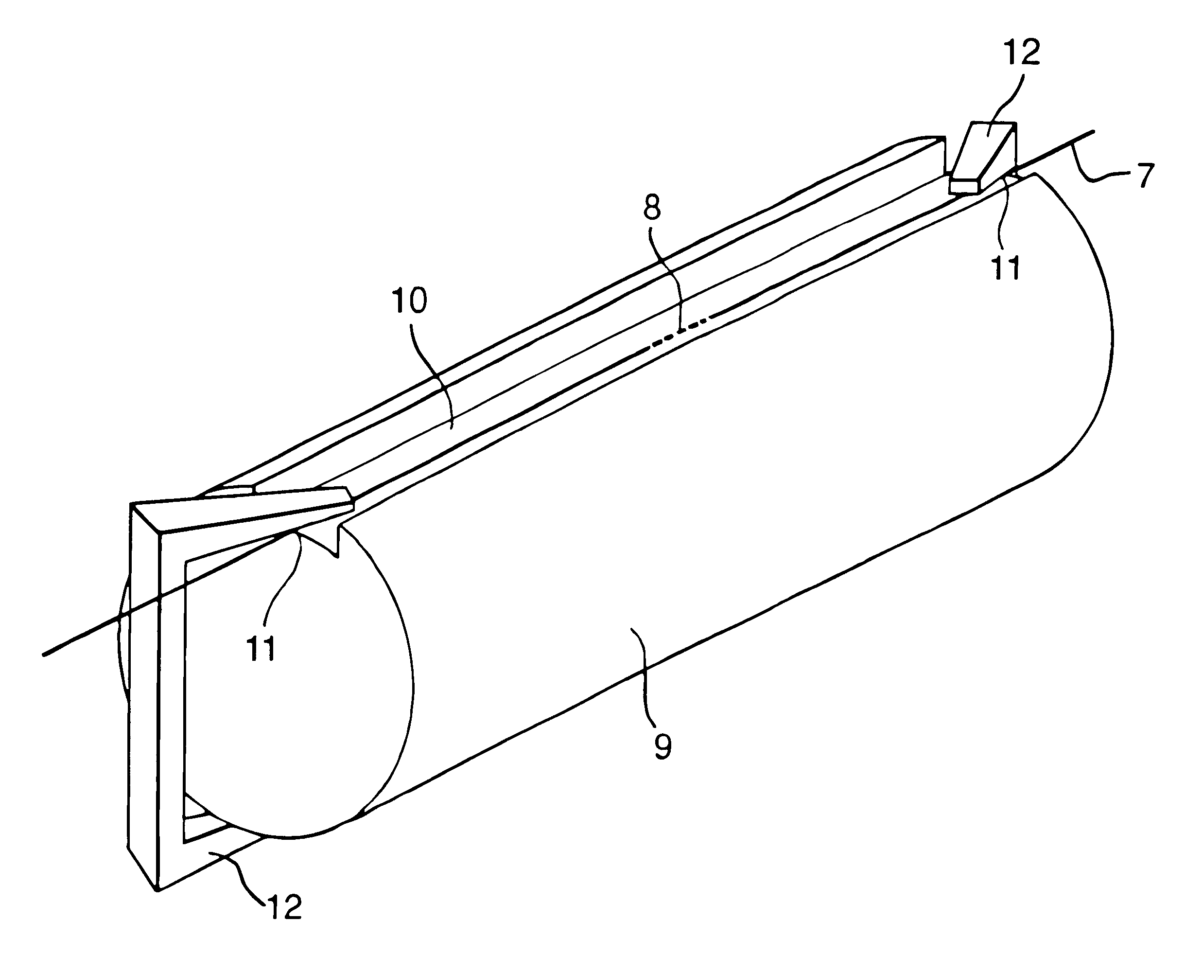
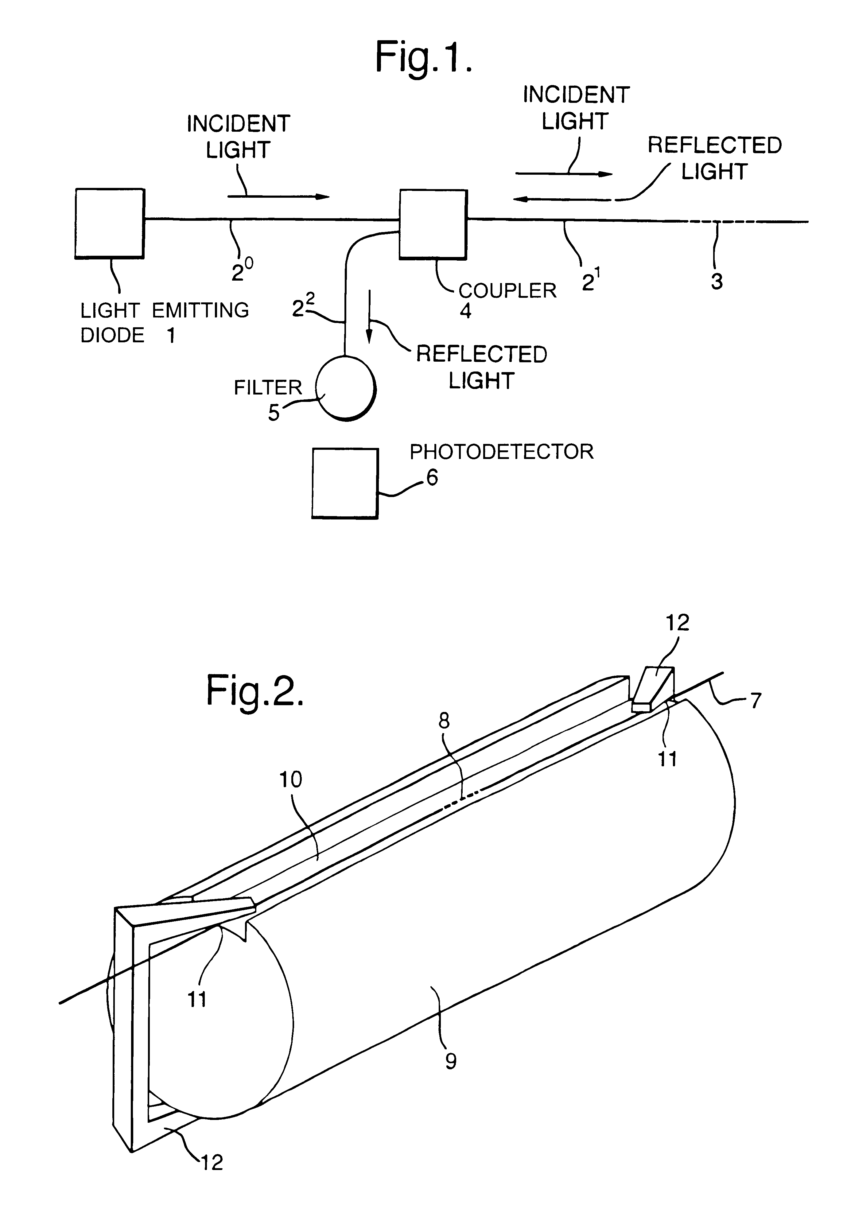
FIG. 1 shows an example of a framework of a temperature sensing apparatus in accordance with the present invention comprising a broad-band light source, in this case an extra-bright light emitting diode (ELED) 1; single-mode optic fibres 2 containing an in-fibre grating structure 3; a directional coupler 4; an optical filter 5 and a photodetector 6. The in-fibre grating structure 3 is fixedly mounted on a substantially rigid substrate (not shown). In a conventional apparatus, the in-fibre grating structure 3 is free-standing i.e. it is not fixedly mounted on a substrate. The light produced by the ELED 1 is of 1550 nm wavelength with a 40 nm bandwidth and is transmitted through the fibre 2.sup.0 and 2.sup.1 onto the grating 3. The grating 3 reflects a narrow bandwidth of light back through the fibre 2.sup.1 through the directional coupler 4 and fibre 2.sup.2 into the optical filter 5. The filter 5 is chosen so that the intensity of light transmitted to the photodetector 6 depends on ...


PUM

PropertyMeasurementUnit
wavelengthaaaaaaaaaa
refractive indexaaaaaaaaaa

Abstract

Temperature sensing apparatus comprises a source of electromagnetic radiation (1), a wavelength-selective element (3) which interacts with radiation emitted from the source (1) and a detection system (6) which monitors radiation from the wavelength-selective element (3). The wavelength-selective element (3) is fixedly mounted on a substantially rigid substrate (not shown). The apparatus can be used for temperature sensing in aquatic environments.

Description

1. Field of the InventionThis invention relates to a temperature sensing apparatus. More particularly, this invention relates to temperature sensing apparatus such as those using diffraction gratings and other wavelength-selective elements.2. Discussion of Prior ArtBragg diffraction gratings have been used to measure temperature, pressure and strains, particularly in the oceanographic environment (S. W. James et al., Electronics Letters, 32(12), 1996 and J. Jones, OFS 12, p.36-39, 1997), by their incorporation into apparatus which monitor the change in the diffraction condition as the temperature, pressure and strain change. A typical sensing apparatus comprises a light source, a diffraction grating (which diffracts the incident light in a manner dependent on the pressure, temperature and non-hydrostatic stress) and a detector which monitors the light diffracted bu. the grating.In such an apparatus, changes in the Bragg diffraction condition occur due to variations in pressure, temp...

Claims


Application Information

Patent Timeline
Patent Type & Authority Patents(United States)
IPC IPC(8): G01K11/00G01K11/32G01K11/12
CPCG01K11/3206
Inventor CRANCH, GEOFFREY ACRICKMORE, ROGER
Owner OPTASENSE HLDG LTD
Why Eureka
Try Eureka