Method and apparatus for post-polish thickness and uniformity control

a technology of uniformity control and method, applied in the direction of manufacturing tools, grinding machine components, lapping machines, etc., can solve the problems of non-uniformity of the pre-polish surface of the process layer, the difficulty of controlling the post-polish thickness of the process layer on a run-to-run basis, and the drift of the chemical mechanical polishing process from its optimized sta

Inactive Publication Date: 2003-04-01
GLOBALFOUNDRIES INC
View PDF4 Cites 83 Cited by
  • Summary
  • Abstract
  • Description
  • Claims
  • Application Information

AI Technical Summary

Problems solved by technology

Typically, a chemical mechanical polishing device is optimized for a particular process, but because of chemical and mechanical changes to the polishing pad during polishing, degradation of process consumables, and other processing factors, the chemical mechanical polishing process may drift from its optimized state.
In addition to process drift, pre-polish surface non-uniformity of the process layer may also contribute to producing variations across the post-polish surface of the wafer.
Because of variation in the incoming thickness and profiles of individual process layers, changing the mean polish rate as well as the uniformity makes it difficult to control post-polish thickness of a process layer on a run-to-run basis.

Method used


Image

  • Method and apparatus for post-polish thickness and uniformity control
  • Method and apparatus for post-polish thickness and uniformity control
  • Method and apparatus for post-polish thickness and uniformity control

Examples


Embodiment Construction

Illustrative embodiments of the invention are described below. In the interest of clarity, not all features of an actual implementation are described in this specification. It will of course be appreciated that in the development of any such actual embodiment, numerous implementation-specific decisions must be made to achieve the developers' specific goals, such as compliance with system-related and business-related constraints, which will vary from one implementation to another. Moreover, it will be appreciated that such a development effort might be complex and time-consuming, but would nevertheless be a routine undertaking for those of ordinary skill in the art having the benefit of this disclosure.

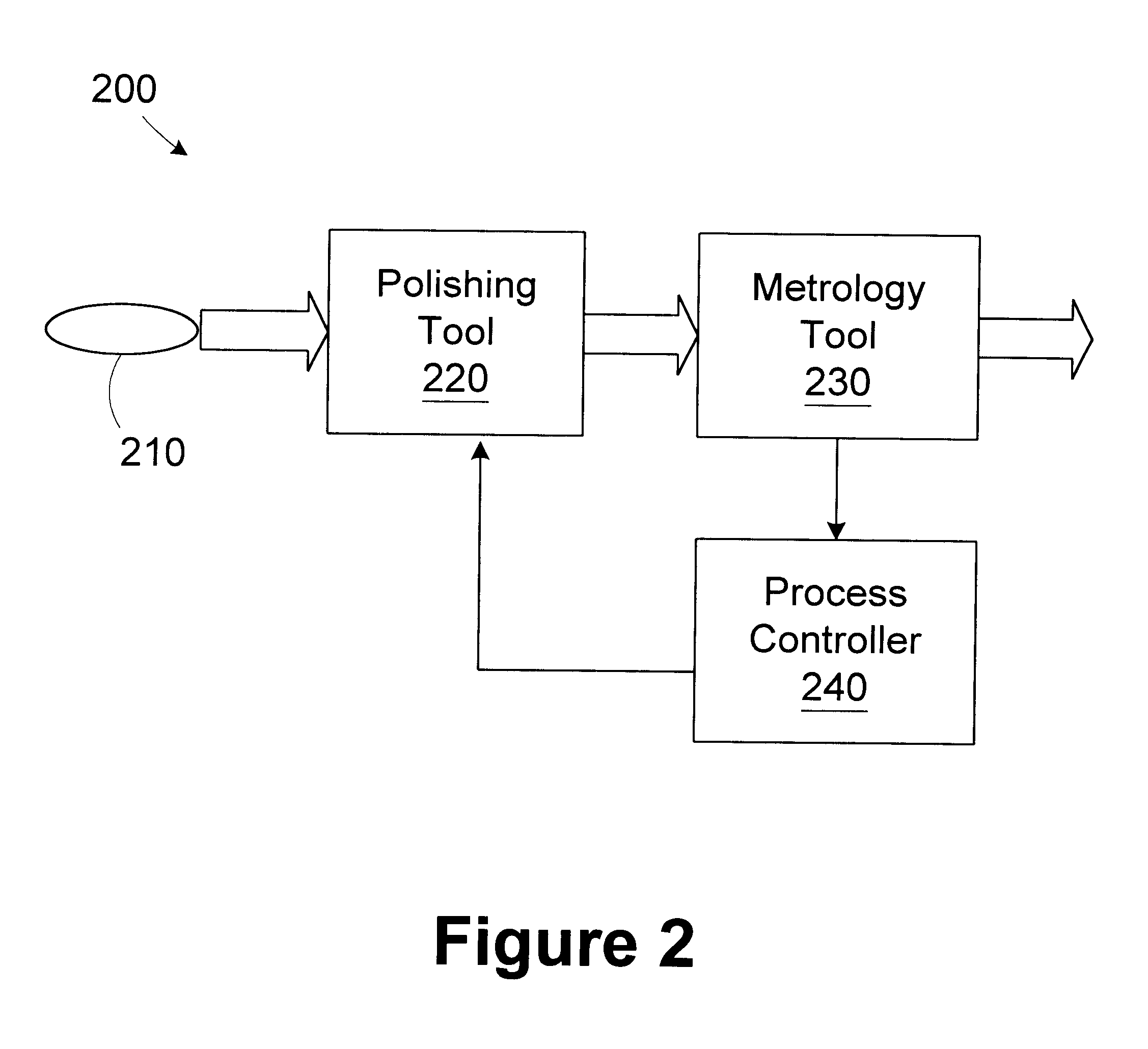
Referring to FIG. 2, a simplified diagram of an illustrative processing line 200 for processing wafers 210 in accordance with one illustrative embodiment of the present invention is provided. The processing line 200 includes a polishing tool 220 for polishing the wafers 210 in accordan...


PUM

PropertyMeasurementUnit
thicknessaaaaaaaaaa
pressureaaaaaaaaaa
gas pressureaaaaaaaaaa

Abstract

A method for polishing wafers includes providing a wafer having a process layer formed thereon; providing a polishing tool having a plurality of control zones and being adapted to polish the process layer based on an operating recipe, the operating recipe having a control variable corresponding to each of the control zones; measuring a pre-polish thickness profile of the process layer; comparing the pre-polish thickness profile to a target thickness profile to determine a desired removal profile; determining values for the control variables associated with the control zones based on the desired removal profile; and modifying the operating recipe of the polishing tool based on the values determined for the control variables. A processing line includes a polishing tool, a metrology tool, and a process controller. The polishing tool is adapted to polish a wafer having a process layer formed thereon based on an operating recipe. The polishing tool includes a plurality of control zones and the operating recipe includes a control variable corresponding to each of the control zones. The metrology tool is adapted to measure a pre-polish thickness profile of the process layer. The process controller is adapted to compare the pre-polish thickness profile to a target thickness profile to determine a desired removal profile, determine values for the control variables associated with the control zones based on the desired removal profile, and modify the operating recipe of the polishing tool based on the values determined for the control variables.

Description

1. Field of the InventionThis invention relates generally to semiconductor device manufacturing and, more particularly, to a method and apparatus for post-polish thickness and uniformity control.2. Description of the Related ArtChemical mechanical polishing (CMP) is a widely used means of planarizing silicon dioxide as well as other types of process layers on semiconductor wafers. Chemical mechanical polishing typically utilizes an abrasive slurry disbursed in an alkaline or acidic solution to planarize the surface of the wafer through a combination of mechanical and chemical action. Generally, a chemical mechanical polishing tool includes a polishing device positioned above a rotatable circular platen or table on which a polishing pad is mounted. The polishing device may include one or more rotating carrier heads to which wafers may be secured, typically through the use of vacuum pressure. In use, the platen may be rotated and an abrasive slurry may be disbursed onto the polishing ...

Claims


Application Information

Patent Timeline
Patent Type & Authority Patents(United States)
IPC IPC(8): B24B21/04B24B21/10B24B49/04B24B37/04B24B49/02
CPCB24B21/10B24B49/04B24B37/042B24B37/013
Inventor PASADYN, ALEXANDER J.RAEDER, CHRISTOPHER H.TOPRAC, ANTHONY J.
Owner GLOBALFOUNDRIES INC
Why Eureka
Try Eureka