
Swash plate of swash plate type compressor

Inactive Publication Date: 2003-04-01
TAIHO INDUSTRIES CO LTD
View PDF5 Cites 14 Cited by
  • Summary
  • Abstract
  • Description
  • Claims
  • Application Information

AI Technical Summary

Benefits of technology

It is, therefore, an object of the present invention to improve wear resistance of a flame-sprayed copper-alloy,layer of a swash-plate type compressor.
In the present invention, the binder effect for forming the composite material can be realized when at least the aluminum-alloy is melted. Copper and aluminum inherently exhibit good compatibility and are appropriate for bonding.

Problems solved by technology

From another point of view, for example, Pb of a Cu--Pb alloy and Si of an Al--Si alloy impair the properties of the matrix of the other alloy, so that no useful composite structure is obtained.

Method used


Image

  • Swash plate of swash plate type compressor
  • Swash plate of swash plate type compressor
  • Swash plate of swash plate type compressor

Examples


example 1

60 weight % of a Cu-10 weight % of Pb-10 weight % of Sn alloy atomized powder (30 .mu.m of average particle diameter) and 40 weight % of aluminum-alloy atomized powder (atomized powder of A2024 aluminum alloy, to which 40 weight % of Si is added, 10 .mu.m of average particle diameter) were mixed. A commercially available pure-aluminum rolled sheet was subjected to shot blasting using steel grids (0.7 mm of size) so as to roughen the surface of a substrate to Rz 45 .mu.m. Flame spraying was carried out on the roughened substrate to a thickness of 250 .mu.m. An HVOF type flame-spraying machine (DJ. product of Sulzer Meteco) was used for the flame spraying. The flame spraying was carried out under the following conditions.

Oxygen Pressure: 1.03 MPa, 150 psi

Fuel Pressure: 0.69 MPa, 100 psi

Flame-Spraying Distance: 180 mm

Flame-Spraying Thickness: 250 .mu.m

Hardness of the flame-sprayed layer was Hv 260-300. In addition, the entire composition was 36% of Cu, 31% of Al, 3% of Pb, 22% of Si, 4...

example 2

The same flame-spraying as in Example 1 was repeated except that the atomized copper-alloy powder of Example 1 was replaced with a Cu-24 weight % of Pb-4 weight % of Sn alloy atomized powder. The same wear test as in Example 1 was carried out. The results are shown in Table 3. Hardness of the flame-sprayed layer was Hv 220-280. In addition, the entire composition was 36% of Cu, 32% of Al, 7% of Pb, 23% of Si, and 2% of Sn.

example 3

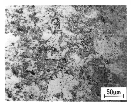
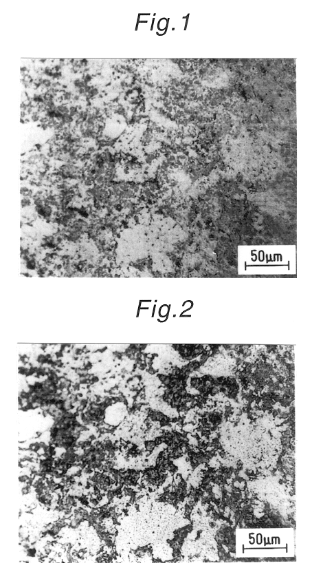
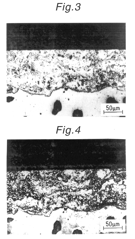
75% by weight of a Cu-10 weight % of Pb-4 weight % of Sn alloy atomized powder (60 .mu.m of average particle-diameter) and 25% by weight of aluminum-alloy atomized powder (atomized powder of A2024 aluminum alloy, to which 40 weight % of Si was added, 100 .mu.m of average particle diameter) were mixed. A commercially available pure-aluminum was treated under the same conditions as in Example 1. The flame spraying was carried out under the same conditions as in Example 1. FIG. 1 shows the microscopic structure of the surface of the flame-sprayed layer without etching. FIG. 2 shows the microscopic structure of the surface of the flame-sprayed layer with etching by Grad liquid (5 g of ferric chloride, 100 cc of hydrochloric acid, and 100 cc of water). FIG. 3 shows the microscopic structure of the cross-sectional surface of the flame-sprayed layer without etching for 5 seconds. FIG. 4 shows the microscopic structure of the cross-sectional surface of the flame-sprayed layer with etching b...


PUM

PropertyMeasurementUnit
Percent by massaaaaaaaaaa

Abstract

In order to improve the wear resistance of the swash plate of a swash-plate type compressor, on which plate copper alloy is flame-sprayed, a composite material, which consists of copper or first copper alloy (for example Cu-Pb alloy) including at least unmelted phase and aluminum or first aluminum alloy (for example Al-Si alloy) including at least melted phase, is flame sprayed on the sliding surface with a shoe.

Description

The present invention relates to a swash plate of a swash-plate type compressor. The present invention relates to such technical fields as a swash-plate type compressor, the sliding layer having, a composite structure, flame-spraying technique, aluminum-alloy sliding material and copper-alloy sliding material.BACKGROUND TECHNIQUEIn the swash-plate type compressor, a swash-plate is rigidly secured obliquely to a rotary shaft or is secured obliquely to a rotary shaft in such a manner that its slanting angle is variable. The compression and expansion are carried out by means of rotating the swash-plate, which increases or decreases the volume of a partition space within a compressor, depending upon the rotation of the rotary shaft.Such swash plate is caused to slide on a sliding member referred to as a shoe, and gas-tight sealing is attained between the both members. The cooling medium can therefore be compressed and expanded in the stated space.A salient point in the sliding condition...

Claims


Application Information

Patent Timeline
IPC IPC(8): F04B27/10F04B27/08C22C9/01C22C9/02C22C9/04C22C9/06C22C9/08C22C9/10C22C21/00C23C4/06C23C4/08C23C4/18
CPCF04B27/1054Y10T428/12736F05C2201/0475F05C2201/049F05C2201/903F05C2203/06Y10S428/937Y10T428/12694Y10T428/1266Y10T428/12917Y10T428/12903Y10T428/12625Y10T428/12764Y10T428/12687Y10T428/1275Y10T428/12535Y10T428/12757Y10T428/12667F05C2201/021F04B27/08
Inventor TOMIKAWA, TAKASHIYAMADA, TOYOKAZU
Owner TAIHO INDUSTRIES CO LTD
Features
  • Generate Ideas
  • Intellectual Property
  • Life Sciences
  • Materials
  • Tech Scout
  • Unparalleled Data Quality
  • Higher Quality Content
  • 60% Fewer Hallucinations
Learn More