Perfusion chamber for electrophysiological testing of oocytes

a perfusion chamber and electrophysiological testing technology, applied in the field of holding chambers, can solve the problems of inability to achieve parallel testing, inconvenient automatic insertion of electrodes, and considerable skill and manipulation,

Inactive Publication Date: 2003-04-01
MDS ANALYTICAL TECH US
View PDF23 Cites 36 Cited by
  • Summary
  • Abstract
  • Description
  • Claims
  • Application Information

AI Technical Summary

Problems solved by technology

The configuration of the chamber often impedes direct access to the oocyte, thereby complicating automatic insertion of the electrodes.
Moreover, considerable skill and manipulation is required to place the oocyte in the appropriate position within the chamber, which is prohibitive for automated, rapid-throughput, parallel-testing applications.
Finally, the geometries of the structures used

Method used


Image

  • Perfusion chamber for electrophysiological testing of oocytes
  • Perfusion chamber for electrophysiological testing of oocytes
  • Perfusion chamber for electrophysiological testing of oocytes

Examples


Embodiment Construction

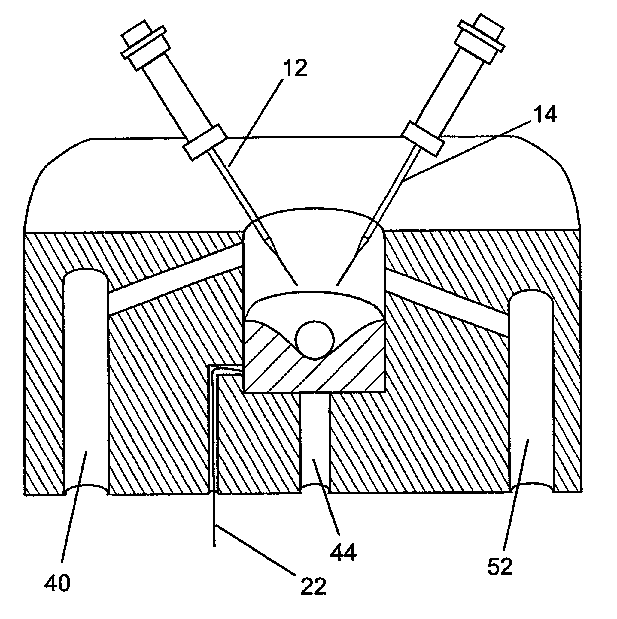
The heart of this invention lies in the idea of utilizing a sufficiently porous material to support an oocyte in a perfusion chamber so as to permit its total exposure to the continuous, uniform perfusion of its membrane with a test solution. Further, the geometry of the support site is optimized to facilitate the introduction of the oocyte, to evenly distribute the pressure exerted on the oocyte's membrane by the support structure, and to firmly place the oocyte within the automatic reach of voltage-clamp hardware. These improvements have enabled the implementation of a multiple-chamber, continuous-operation, automated electrophysiology recording device.

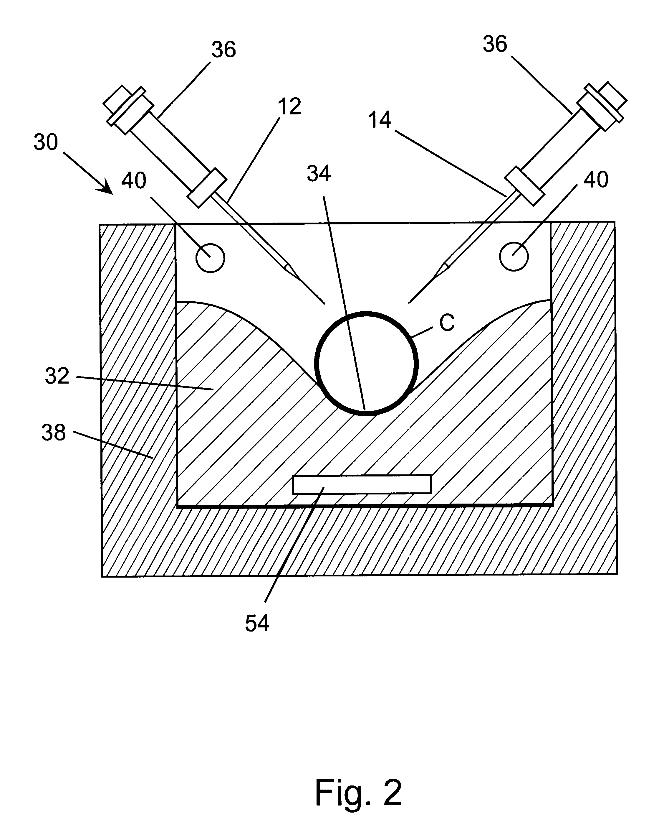
Referring to the figures, wherein the same reference numerals and symbols are used throughout for like parts, FIG. 2 is a sectioned schematic illustration of a perfusion chamber 30 according to the invention. The drawing shows a porous support structure 32 in a vertical section through the center of a holding well 34 sized for retai...


PUM


Abstract

A perfusion chamber includes a porous oocyte support structure. A continuously sloped top surface and a receiving well in the support structure entrap the underside of the oocyte, thereby localizing the cell in a predetermined fixed position within the reach of dedicated voltage-clamp microelectrodes. A test solution is delivered continuously at the top of the chamber, above the oocyte, and withdrawn from the bottom of the chamber, below the oocyte. The porosity of the support material enables the continuous perfusion of test solution around the membrane of the oocyte, including its bottom portion that is held firmly in contact with the holding well. The geometry of the holding well is selected such as to ensure the automatic and precise placement of the oocyte by gravity and to optimize the pressure distribution over its membrane, thereby minimizing the probability of rupture or other damage to the cell. The entire top surface of the support structure is sloped inward toward the substantially central well, and the bottom of the well is contoured to conform to the shape of an oocyte of average size.

Description

1. Field of the InventionThis invention is related in general to holding chambers for carrying out identification of targets in the drug discovery process and, in particular, to a perfusion chamber for measuring electrophysiological responses from frog oocytes.2. Description of the Related ArtThe modern process of drug discovery involves a number of distinct steps. Various possible sources for drugs are first investigated to generate libraries of compounds to test for potential activity. Such compounds are preferably produced using combinatorial chemistry, and are typically synthesized from theoretical considerations or on the basis of templates derived from natural products harvested from around the world and previously tested for activity. These libraries of compounds are then screened to assess their effects on particular targets of interest. As used in the art, "targets" are the entities acted upon by drugs, normally proteins and receptors that transmit information within and be...

Claims


Application Information

Patent Timeline
IPC IPC(8): C12M3/00C12M1/34
CPCC12M41/46C12M29/10
Inventor HARRIS, ERIC W.LANTHORN, THOMAS H.KILDAL, MAURICE A.
Owner MDS ANALYTICAL TECH US
Why Eureka
Try Eureka