Well tending method and apparatus

a well and equipment technology, applied in the field of well tending methods and equipment, can solve the problems of snake injury, water management problems, wasting time and money, etc., and achieve the effect of limiting the negative consequences of the problem

Inactive Publication Date: 2003-04-01
KOSTER WALLACE C
View PDF11 Cites 17 Cited by
  • Summary
  • Abstract
  • Description
  • Claims
  • Application Information

AI Technical Summary

Benefits of technology

Accordingly, the objects and advantages of the invention are:
A) to provide a method to monitor, control, record, and transmit operational parameters of an aquifer test, municipal well, dewatering project, pump and treat remediation project, or similar activity.
B) to provide an apparatus to monitor, control, record, and transmit operational parameters of an aquifer test, municipal well, dewatering project, pump and treat remediation project, or similar activity.
C) to provide a remotely controlled monitoring apparatus and method that can be used to test an aquifer, operate a municipal well, oversee a dewatering project, direct groundwater flow in a pump and treat remedi

Problems solved by technology

Municipalities, agricultural concerns, construction projects, and remediation projects all encounter water management issues.
Aquifer testing is an arduous task.
They must set-up numerous pieces of equipment, wasting time and money.
Furthermore, workers are subject to injury from insects, snakes, and from falls or muscular strains due to standing or walking over uneven and/or slippery ground.
As a result of these inhospitable conditions, data collected during the testing is often "noisy."
Instead of watching the equipment, making adjustments to the flow valve as necessary, and taking the required readings, the workers' vigilance is often compromised by the inhospitable conditions outlined above.
Even under optimal conditions, maintaining a constant flow by manual means is nearly impossible under rapidly changing wate

Method used


Image

  • Well tending method and apparatus
  • Well tending method and apparatus
  • Well tending method and apparatus

Examples


Embodiment Construction

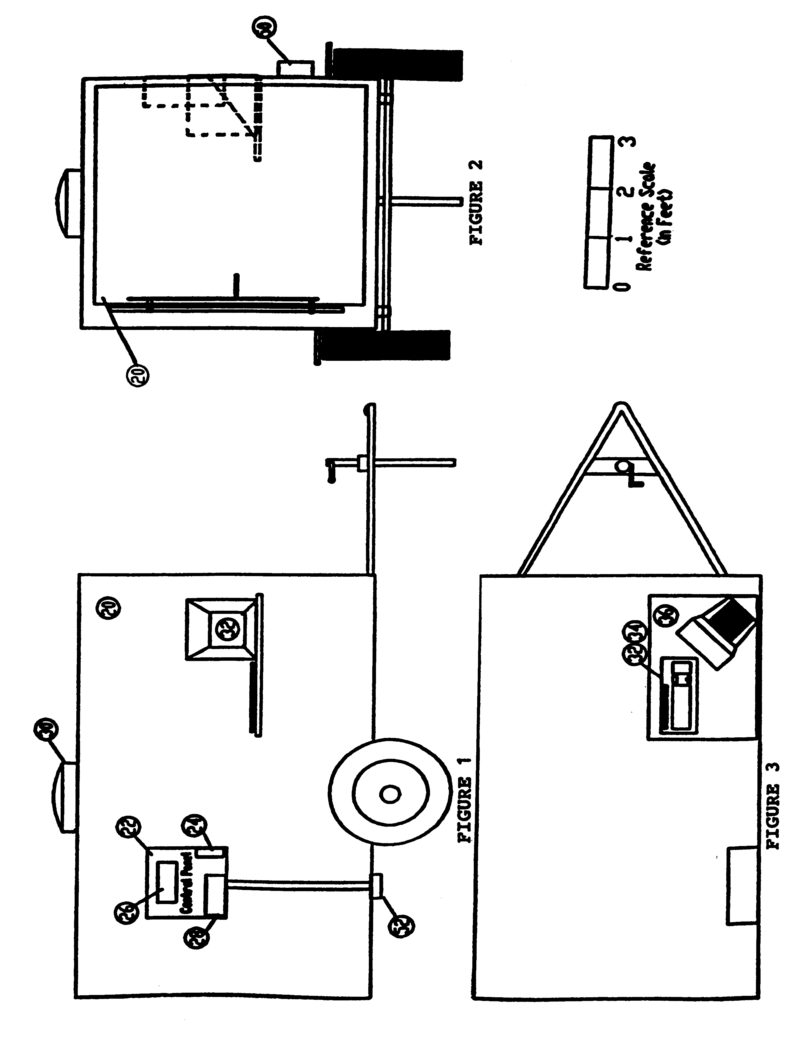
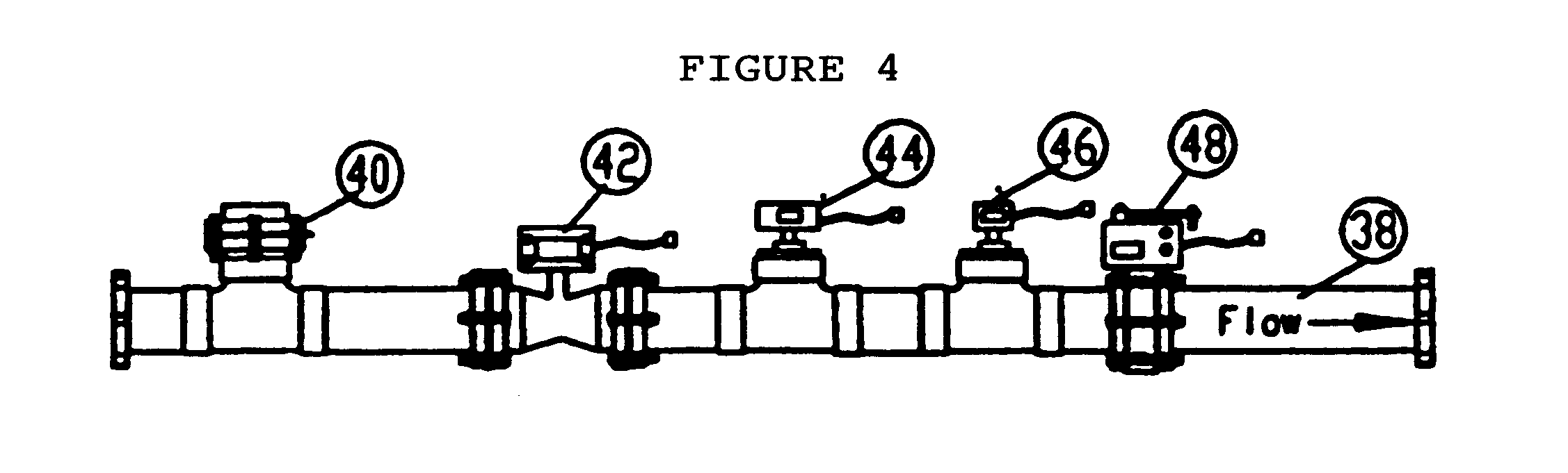
The following illustrates a preferred embodiment of the invention for aquifer or well testing. As shown in FIG. 5A, a trailer 20 is connected via sensor cables 60 from the flow measurement / control assembly signal / power junction box 50 to a flow measurement / control assembly (hereinafter "FMCA") 38, to a down well pressure transducer 54, and to an electrical power source / power generator 56, where connections are made to an electrical current sensor 64, an oil temperature sensor 66, and a fuel sensor 68. Furthermore, the trailer 20 is connected via power cables 62 from a trailer power feed junction box 52 to the power generator 56. A pump 58 is connected to the electrical power source 56 via power cables 62.

As shown in FIGS. 1-3, the trailer 20 houses a control panel 22, an autodialer 24, a programmable logic controller (hereinafter "PLC") 26, a cellular telephone and modem interface 28, a supervisory / control and data acquisition (hereinafter "SCADA") computer 32 incorporating the flow...


PUM

PropertyMeasurementUnit
Temperatureaaaaaaaaaa
Lengthaaaaaaaaaa
Flow rateaaaaaaaaaa

Abstract

A method and apparatus for monitoring, controlling, recording, and transmitting operational parameters of an aquifer test, municipal well, dewatering project, pump and treat remediation project, or similar activity is presented. Water from a water source, typically a well, is directed through a flow control and monitoring assembly containing sensors to measure well parameters. Sensor readings are sent to a computing device for processing. Discrepancies are detected and operational parameters adjusted to avoid discrepancy-related failures. On-site and off-site personnel interface with the system through a man-machine interface or telephonic communication means, respectively. Performance and efficiency are determined in terms of drawdown, yield, rate of flow, residual drawdown, and specific capacity.

Description

Not applicable.Not applicable.1. Field of the InventionThis invention relates to a method and apparatus, specifically to a method and apparatus used to monitor, control, and manage operational parameters associated with well pumping activities, especially in regard to drawdown and yield of a well or aquifer.2. Discussion of Prior ArtWater management is important in many fields. Municipalities, agricultural concerns, construction projects, and remediation projects all encounter water management issues. Whether it is testing a new source of water, controlling operational parameters of an operating well, monitoring an excavation site for possible water-related landmass failures, or directing groundwater flow in pump and treat remediation projects, water management plays an important role in modern industry.Municipalities and agricultural concerns need water in order to function. One of the principal sources of water for municipal and agricultural supply is groundwater via groundwater p...

Claims


Application Information

Patent Timeline
IPC IPC(8): G06F19/00G05B15/02G05B23/02
CPCG05B15/02G05D7/0635E21B47/12E21B47/00
Inventor KOSTER, WALLACE C.
Owner KOSTER WALLACE C
Why Eureka
Try Eureka