Coiled optical assembly and fabricating method for the same

a technology of optical assembly and coiled ends, which is applied in the direction of clad optical fiber, glass optical fibre, instruments, etc., can solve the problems of deteriorating signal quality, large wavelength dispersion, and optical signal distortion

Inactive Publication Date: 2003-04-08
SUMITOMO ELECTRIC IND LTD
View PDF24 Cites 23 Cited by
  • Summary
  • Abstract
  • Description
  • Claims
  • Application Information

AI Technical Summary

Problems solved by technology

However, when transmission is carried out in the wavelength band of 1.55 .mu.m by using a single-mode optical fiber whose zero-dispersion wavelength is in the 1.3-.mu.m band (1.3 SMF), which is employed in conventional optical transmission lines, then a large wavelength dispersion occurs and distorts optical signals, there by deteriorating the signal quality.
Nevertheless, since a wide-band DCF has a large bending loss in general, it may yield a large transmission loss in the 1.55-.mu.m band, i.e., transmission wavelength band, when formed into a coil having a small diameter.
Increasing the coil diameter, however, is unfavorable in that the dispe

Method used


Image

  • Coiled optical assembly and fabricating method for the same
  • Coiled optical assembly and fabricating method for the same
  • Coiled optical assembly and fabricating method for the same

Examples


example b

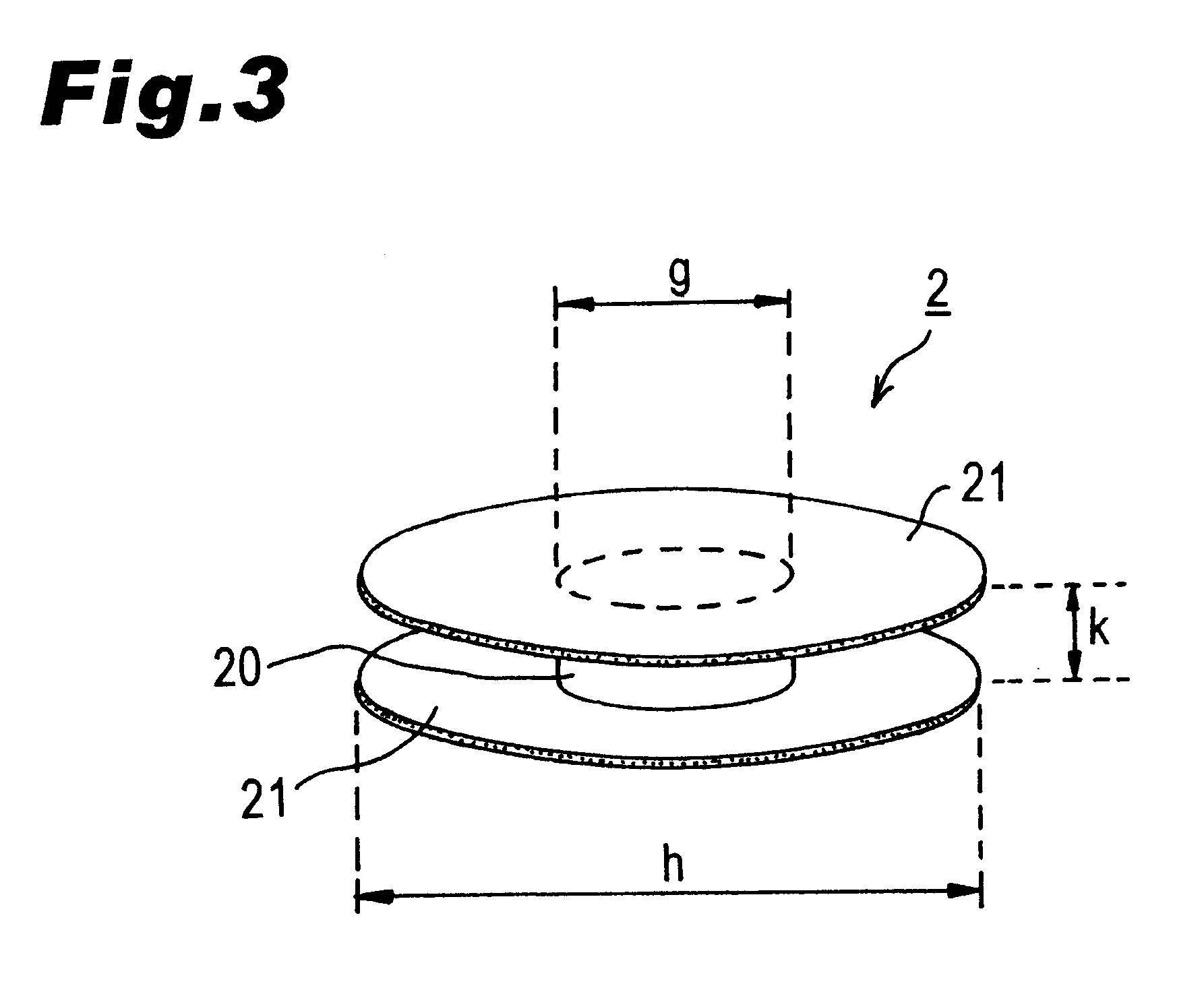
Around a bobbin 2 made of aluminum in which g=60 mm and k=45 mm, about 190 plies of a DCF, identical to that of Example A, having a length of 13 km were wound with a winding pitch of 0.28 mm at each of three kinds of take-up tensions of 20 gf, 25 gf, and 50 gf, whereby three kinds of dispersion compensators were produced.

FIG. 26 is a graph plotting thus obtained three kinds of dispersion compensators in terms of take-up tension and transmission loss value at a wavelength of 1.55 .mu.m which are indicated by the abscissa and the ordinate, respectively. The broken line is a transmission loss value shown for comparison as with FIG. 25. The transmission value was 2.54 dB / km and 1.05 dB / km when the take-up tension was 50 gf and 25 gf, respectively, thereby becoming smaller as the take-up tension was lower. At the take-up tension of 20 gf, however, the transmission loss value increased to 2.95 dB / km. It is assumed to be because the take-up tension was so low that the winding of the fiber ...

example c

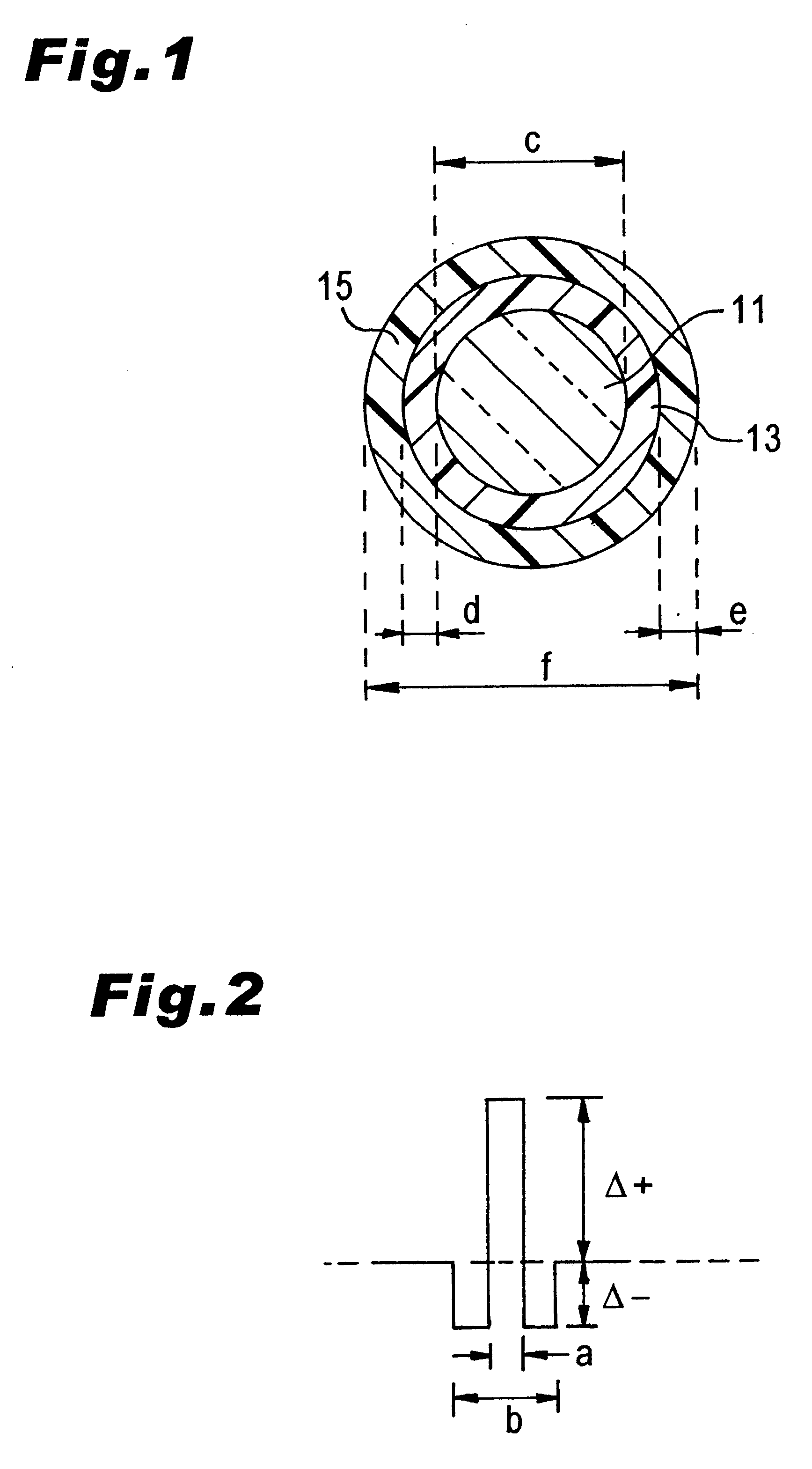
Around a bobbin 2 made of aluminum in which g=100 mm and k=18 mm, about 210 plies of a DCF having a length of 8 km and the characteristics shown in the following Table (see FIGS. 1 and 2 for its form and refractive index profile, respectively) were wound with a winding pitch of 0.40 mm at each of four kinds of take-up tensions of 20 gf, 30 gf, 40 gf, and 50 gf, whereby four kinds of dispersion compensators were produced. This DCF has the specific characteristics shown in the following Table.

FIG. 27 is a graph plotting thus obtained four kinds of dispersion compensators in terms of take-up tension and transmission loss value at a wavelength of 1.55 .mu.m which are indicated by the abscissa and the ordinate, respectively. The broken line also indicates take-up tension and transmission loss value by the abscissa and the ordinate, respectively. The broken line indicates the transmission loss value (0.45 dB / km) at a wavelength of 1.55 .mu.m before the coil is taken up. The transmission l...

example d

Around a bobbin 2 made of aluminum in which g=80 mm and k=45 mm, about 190 plies of a DCF having a length of 14 km and the characteristics shown in the following Table (see FIGS. 1 and 2 for its form and refractive index profile, respectively) were wound at a take-up tension of 35 gf with each of four kinds of winding pitches of 0.2 mm, 0.4 mm, 0.6 mm, and 1.0 mm, whereby four kinds of dispersion compensators were produced. This DCF has the specific characteristics shown in the following Table.

FIG. 28 is a graph plotting thus obtained four kinds of dispersion compensators (with black circles) in terms of winding pitch and PMD which are indicated by the abscissa and the ordinate, respectively. While PMD was 1.68 ps when the winding pitch was 0.2 mm, it became 1.12 ps, 0.94 ps, and 0.90 ps at the winding pitches of 0.4 mm, 0.6 mm, and 1.0 mm, respectively. Hence, it has been confirmed that PMD can be lowered when the winding pitch is made greater as compared with the diameter of the D...


PUM


Abstract

After a wide-band DCF is wound around a bobbin to form an optical fiber coil 32, the latter is removed from the bobbin and placed into a bundle state (the state where the increase in transmission loss in the wavelength band of 1.55 mum caused by distortions in winding is reduced by 0.1 dB/km or more) released from distortions in winding. A resin 42 is used as a coil-tidying member so as to secure the optical fiber coil 32 to a storage case 40 at four positions. Both ends of the optical fiber coil 32 are connected to pigtail fibers at fusion-splicing parts 44; respectively. Even when the storage case 40 is closed with a lid after the optical fiber coil 32 is secured to the storage case 40 with the resin 42, there remain interstices within the bundle of the optical fiber coil 32 and a space between the optical fiber coil 32 and the storage case 40. As a result, even when the optical fiber coil 32 in a bundle state is accommodated in the storage case 40, transmission loss and the like would not increase.

Description

1. Field of the InventionThe present invention relates to a coiled optical assembly made of a long optical fiber and a fabricating method for the same; and, in particular, to a dispersion compensator for reducing the wavelength dispersion of an optical fiber transmission line in the wavelength band of 1.55 .mu.m, and a fabricating method for the same.2. Related Background ArtLong-distance, large-capacity transmission is possible in the wavelength band of 1.55 .mu.m by means of an optical amplifier operable in the wavelength band of 1.55 .mu.m utilizing an optical fiber doped with erbium (Er) which is a rare-earth element. However, when transmission is carried out in the wavelength band of 1.55 .mu.m by using a single-mode optical fiber whose zero-dispersion wavelength is in the 1.3-.mu.m band (1.3 SMF), which is employed in conventional optical transmission lines, then a large wavelength dispersion occurs and distorts optical signals, there by deteriorating the signal quality. As a ...

Claims


Application Information

Patent Timeline
IPC IPC(8): G02B6/00G02B6/02
CPCH01S3/06704G02B6/4457G02B6/02261G02B6/03627G02B6/02395
Inventor KOYANO, YASUSHISASAOKA, EISUKETANAKA, SHIGERUKOBAYASHI, KOHEIONISHI, MASASHI
Owner SUMITOMO ELECTRIC IND LTD
Why Eureka
Try Eureka